
The AMS1117 series of chips are linear voltage regulators with low voltage drop. If you order a USB powered board with 3.3V (e.g., STM32 microcontrollers or all sorts of sensors and indicators), the AMS1117-3.3 regulator will most likely be installed on this board. Advanced Monolithic Systems make it.
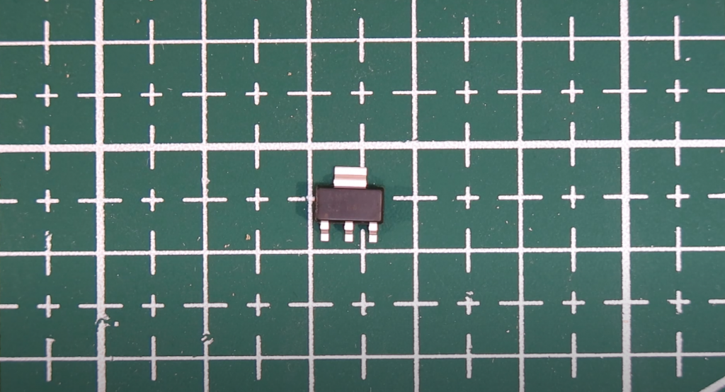
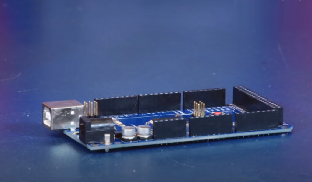
For example, the AMS1117-3.3 in the SOT-223 package is mounted on an STM32F103C8T6 development board.
The AMS1117 is available in different voltages: 1.2V, 1.5V, 1.8V, 2.5V, 2.85V, 3.3V, and 5V.
Besides, there is a modification of the AMS1117, which can be set to the desired voltage from 1.2V to 5V with two external resistors.
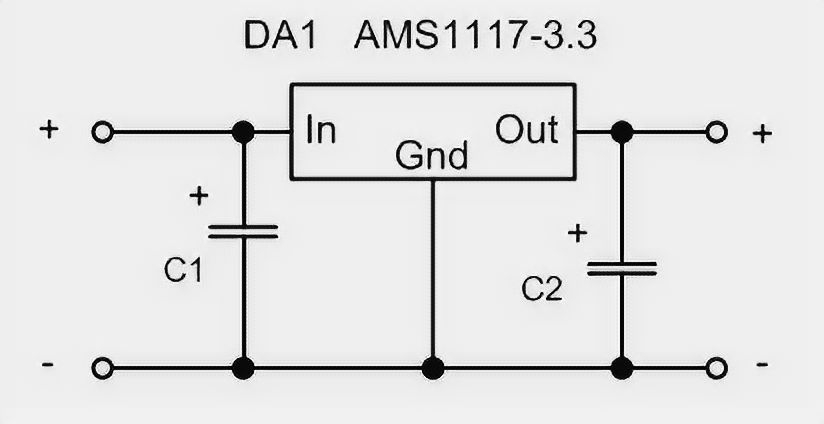
AMS1117 Wiring Diagram
The circuit for switching the regulator to a fixed voltage couldn’t be simpler:
The switching circuit of a stabilizer programmable with resistors is the same as the LM317, for example:
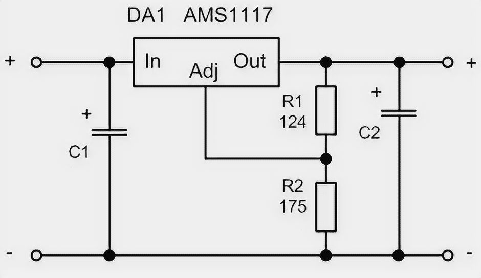
The figure also shows a formula that allows you to calculate the output voltage for the given resistors.
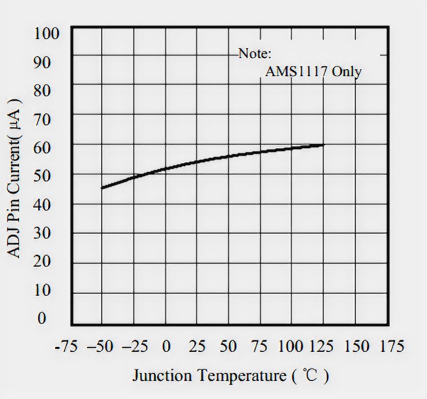
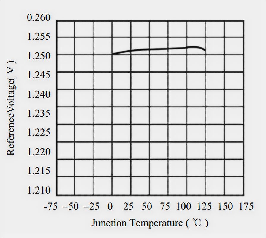
There are graphs of the dependence of the reference voltage and current of the trimmed input on the temperature in the regulator’s documentation. From these graphs, you can see that when the AMS1117 is heated, the output voltage will increase. And if the influence of the current of the trim input can be compensated by reducing the resistors, the change of the reference voltage cannot be compensated in any way.
AMS1117 Pinout
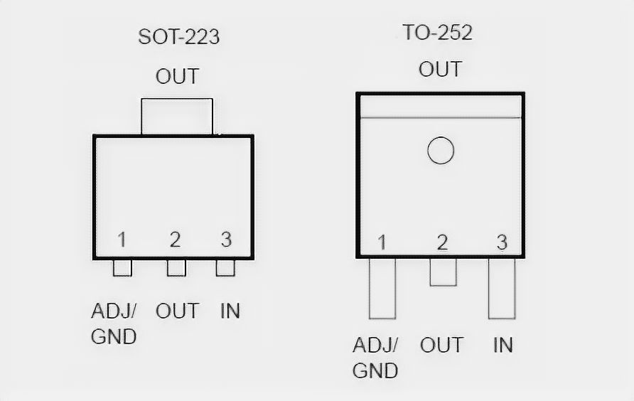
| Pin Number | Pin Name | Description |
| 1 | Adjust/Ground | This pins adjusts the output voltage, if it is a fixed voltage regulator it acts as ground |
| 2 | Output Voltage (Vout) | The regulated output voltage set by the adjust pin can be obtained from this pin |
| 3 | Input Voltage (Vin) | The input voltage which has to be regulated is given to this pin |
AMS1117 Features Description
- Maximum output current is 1A;
- Maximum input voltage 15V;
- Temperature range T = -4 … +257°F;
- Maximum power dissipation for SOT-223 package – Pmax = 0.8 W;
- Maximum power dissipation for TO-252 package – Pmax = 1.5 W;
- Thermal resistance chip-to-chassis for SOT-223 package – Rt = 59°F/W;
- Thermal resistance crystal-to-housing for TO-252 package – Rt = 37°F/W;
- An over-temperature shutdown of the crystal – T = 311°F;
- Thermal hysteresis – ΔT = 77°F.
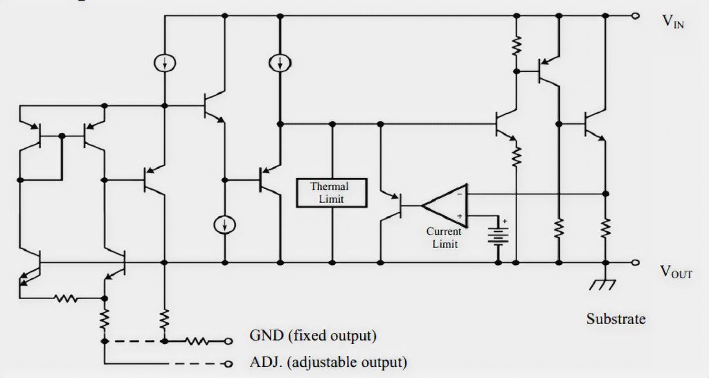
AMS1117 Internal Structure
It is interesting that the fixed voltage stabilizers differ from the “tunable” only in the presence of two additional resistors that determine the voltage. Judging by the picture of the stabilizer structure from the documentation, the setting resistors are present on the crystal. Jumpers determine the choice of what voltage the stabilizer will be programmed to.
AMS1117 Alternatives
Of course, such a popular regulator has analogs: LD1117A, IL1117A, and K1254EN.
The same analog is LM1117, but there are differences:
- The LM1117 can be tuned for voltages from 1.25 V to 13.8 V;
- In addition to the tunable LM1117 comes in voltages of 1.8V; 2.5V; 3.3V, and 5V;
- The SOT-223 version has a maximum current of 800mA.
AMS1117 Usage
The AMS1117 stabilizer can be used in the same circuits as the LM317. Just remember the maximum voltage and output current of the stabilizer.

I don’t understand the following:
1. The voltage is measured between two points. In the diagram, is the U-out terminal connected to a common ground?
2. What is meant when a low voltage drop is advertised on the AVR. For example, the input voltage is 15 V, and the output voltage is 3 V. At what part of the circuit does 12 volts drop? And is 12 volts a small voltage drop? After all, the circuit doesn’t have a transformer and converter to AC voltage? I guess you mean to keep the circuit working with a minimum (1.5…2 V) of the input voltage over the output voltage?
In the schematic, the largest pin of the circuit, which is also the heat sink, is marked in this way. There is no ground in this circuit at all.
By low differential, I mean that it is possible. The LM317 may not get 3.3 volts from 5 volts. It should have a drop of 2 volts or more. But here from 5, we get 3.3, or maybe even from less. The low voltage drop means that the regulator remains functional at a minimum excess of the input voltage over the output voltage.