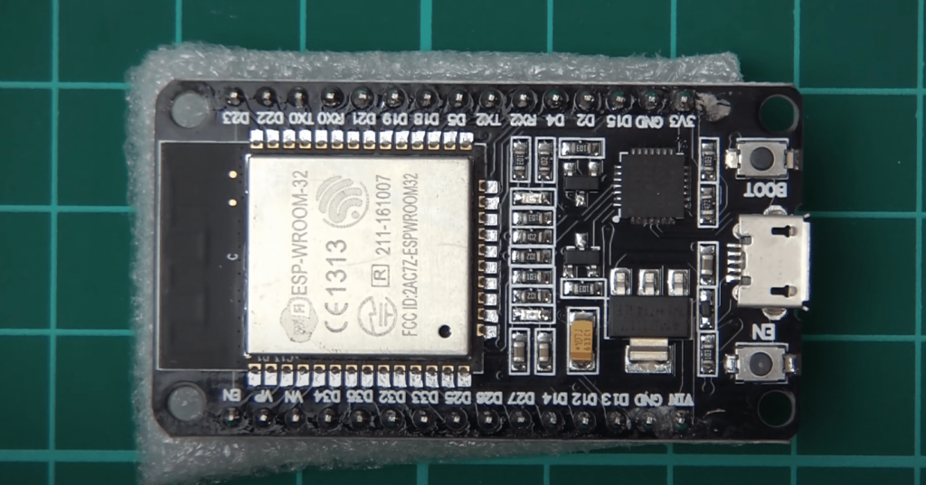
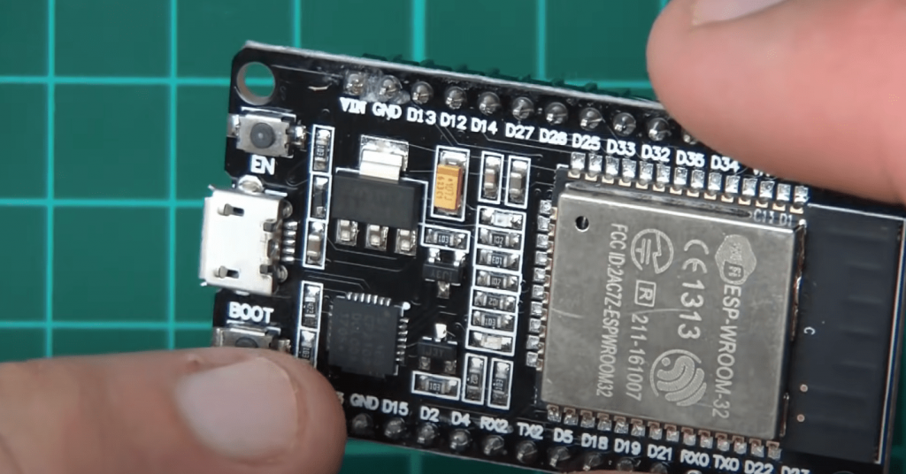
ESP32-WROOM is a module with the ESP32-D0WDQ6 chip, 4MB of Flash memory, and all the necessary interconnects hidden under a metal cover. Pins SCK/CLK, SDO/SD0, SDI/SD1, SHD/SD2, SWP/SD3, and SCS/CMD, namely, GPIO6 to GPIO11, are connected to the integrated SPI flash integrated on the module and are not recommended for other uses.
Next to the shroud is a miniature antenna from the track on the top layer of the PCB in the form of a snake. The metal shroud shields the components of the module and thus improves the electromagnetic properties.
The module is the basis on which industrial devices or debug boards such as ESP32 DevKit or ESP32-Sense Kit are made.
ESP32-WROOM DevKit Pinout
Power Pins
- VIN: A pin for connecting an external voltage source in the range of 5 to 14 volts.
- 3V3: Pin from voltage regulator with an output of 3.3 volts and maximum current of 1 A. The regulator provides power to the ESP32-WROOM module.
- GND: Ground outputs.
I/O Ports
- Digital I/O: 21 pins 1-5, 12-19, 21-23, 25-27, 32 and 33.
General-purpose I/O pins. The pins can be configured for input or output. The logic level of one is 3.3 V, and zero is 0 V. Maximum output current is 12 mA. - Digital Inputs: 4 pins 34-36 and 39.
General-purpose input contacts. It can be configured for input only. - PWM: All I/O pins.
Allows analog values to be output as a 16-bit PWM signal. The maximum number of channels is 16. - ADC: 15 pins 2, 4, 12-15, 25-27, 32-36 and 39.
Allows analog voltage to be represented digitally in 12-bit increments. - DAC: Pins 25(DAC1) and 26(DAC2).
An analog output of a digital-to-analog converter that allows 8-bit voltage levels to be generated. The pins can be used for audio output.
Unlike most Arduino boards, the native voltage of the ESP32 DevKit is 3.3V, not 5V. The outputs for logic one produce 3.3V, and in input mode, expect to accept no more than 3.3V. Higher voltages can damage the microcontroller!
Be careful when connecting peripherals: make sure that they can function correctly in this voltage range.
Interfaces
Each I/O pin of the platform supports hardware interfaces.
- I²C – Used to communicate with peripherals via the serial “I²C” interface.
- SPI – Used to communicate with peripherals over a serial “SPI” interface.
- UART/Serial – For communicating with peripherals via the “UART” interface.
- I²S – Used to send and receive digital audio with other audio devices.
ESP32-D0WDQ6 Chip
The ESP32-D0WDQ6 chip is a System-on-a-Chip (SoC) incorporating a Tensilica Xtensa LX6 dual-core 32-bit processor with 448KB ROM and 520KB SRAM. The chip also includes Wi-Fi/Bluetooth wireless technology, a radio module, a Hall sensor, and a temperature sensor.
The chip requires external Flash memory and other electronic piping. The ESP32-D0WDQ6 crystal is the basis for producing modules with the required peripherals, such as ESP32-WROOM or ESP32-WROVER.