
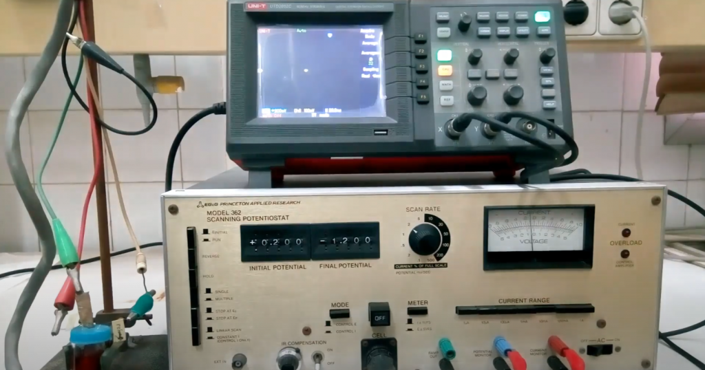
Often, finding a burnt part in a circuit or a broken conductor requires at least “testing” the individual circuits and their elements. This task is unsolvable without an ohmmeter. Along with a voltmeter and an ammeter (as part of a multimeter), it contributes to the craftsman’s work.
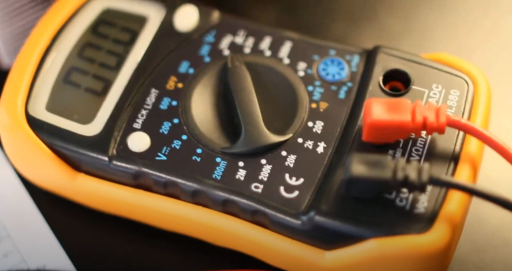
An ohmmeter is an electrical instrument used to measure resistance in a circuit or component. Resistance to the flow of electrical current measures resistance in an electrical circuit. The unit of measurement of electrical resistance is ohms (Ω).
An ohmmeter works on the basis that when an ohmmeter applies current to a circuit or component, it measures the resultant voltage and calculates a resistance value using the formula for Ohm’s law V = IR. We can also use an analog and digital multimeter to measure resistance.
When Was the Ohmmeter Invented?
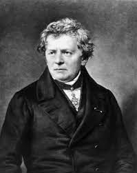 Prior to the invention of the ohmmeter, attempts had been made, not without success, to create a galvanometer sensitive to small currents. Georg Ohm was the founder of the theory behind the modern ohmmeter. He connected an arrow galvanometer to a battery in series through a resistor with a finite resistance R. He found that the strength of the current linearly depends not only on the battery voltage but also on the value of the resistance that the current passes through. Ohm’s law, discovered by the scientist in 1826, is the basis of electrical safety and the work of ohmmeters.
Subsequently, the operation of the ohmmeter was further developed by another physicist-inventor, Charles Wheatstone. He included the galvanometer in the diagonal of the resistor bridge. The additional resistors are equal in Ra and Rb values. The current flowing through the galvanometer is zero if the measured (Rx) and “pattern” (Rs) resistances are equal. In 1843, Wheatstone published his paper on these experiments. Since then, the ohmmeter has become a full-fledged measuring instrument.
It would never have been possible to name the inventor of the voltmeter. This idea is based on Ohm’s law. A dozen of scientists in the nineteenth and twentieth centuries made efforts to modernize the analog ohmmeter – the contribution of each of them is invaluable.
Anyone familiar with physics and electricity today builds an analog ohmmeter based on a dial milliammeter. A kilohmmeter is built based on a microampere meter or millivoltmeter, and a megohmmeter on the basis of a voltmeter, a giga-, and teraohmmeter based on a kilohmmeter. The disadvantage of ohmmeters, which measure resistance from fractions of ohms to one kilohm, is the significant consumption of battery current of 1-3 amps per hour (the time during which the probes are short-circuited). This forces the user to use a battery. A calibration variable resistor is included in the circuit to calibrate the instrument to the ohmic scale properly.
Ohmmeter Features and Construction
The ohmmeter includes:
- an arrow galvanometer;
- stabilized power supply (in the simplest case – battery);
- resistance store switched to the required one by means of a multi-position switch;
- shunt (to measure resistance less than 1 ohm);
- a variable resistor that adjusts the “zero” before starting the measurements;
- connectors for the connectors to which the leads with the stylus on the other end are connected;
- battery power switch to avoid accidental contact of the probes and leakage of its charge.
There can be two calibration resistors – one adjusts the zero roughly (quickly), the other tens of times more accurately. Calibration is necessary because, over time, the battery discharges, lowering its output voltage under load (short-circuited or measured with equivalent resistance probes). It takes 1-3 seconds. The whole assembly is placed in a shockproof case. For the convenience of taking readings, the galvanometer is most often mounted in the case in a “lying” or “semi-lying” position.
The most important characteristics of an ohmmeter are considered:
- accuracy (accuracy class);
- voltage (EMF) of the battery or battery pack;
- dimensions and weight (it is inconvenient to carry an ohmmeter that does not fit in your pocket);
- shock and vibration resistance (shock-absorbing rubber inserts are provided).
It follows from the latter that the instrument must not be thrown or shaken. The dial meter has a measuring head that is vulnerable to vibration shock. A strong shock can break the balancer’s counterweight, without which its end would catch on the scale. In some cases, the return spring, a flat elastic spiral that returns the pointer to zero after the measuring circuit is opened, can also be damaged.
Ohmmeter Principle of Operation
The principle of operation of the device for measuring resistance is as follows. A variable resistor and a battery (or accumulator) are included in the circuit connection of the galvanometer circuit. According to Ohm’s law, low resistance and high current are balanced, and vice versa. The zero value of an ohmmeter is not on the left as in a voltmeter or ammeter but on the right. The scale is graduated backward. The scale divisions are arranged so that the visual distance on the scale for the same resistance interval is reduced. For example, the graduations are arranged from right to left in the following sequence: 0, 1, 2, 5, 10, 20, 50, 100, 500 ohms, 1 kOhm, 5, 25, 200 kOhm, and “infinity”. The last character is in the leftmost position of the arrow.
With the probes closed (circuit enabled), the resistor is twisted until the arrow of the device stops at the conventional zero of the ohmmeter. This will reduce the device’s current consumption to the values of a milliammeter, which measures the short-circuit current in low-power circuits. So now you can measure the resistance you are looking for.
Ohmmeter Classification
According to the range of resistance, ohmmeters are subdivided into:
- microohmmeters – resistance measurement up to 1 mOhm;
- milliohmmeters – up to 1 ohm – are used to evaluate shunts;
- ohmmeters – up to 1 kOhm – are used for calling lines, windings, electric spirals, diodes, transistors, and other elements;
- kiloohmmeters are 1000 ohms to 1 megohm;
- megohmmeters – up to 1 GOhm;
- hygrometers – up to 1 TOM, used to assess the serviceability of insulation and other non-thermal conductive media;
- teraohmmeters are already used to evaluate the medium that separates strongly separated conductors. Conditionally, the dielectric resistance tends to infinity. The resistance of a vacuum is already so.
Analog Ohmmeter
This is the standard pointer multimeter. It has an arrow interface. It can be complicated – when measuring, the device converts the obtained resistance value into a voltage, according to Ohm’s law, directly proportional to it. The performance of this stage is entrusted to a special node in the circuit of the ohmmeter – an operational amplifier. As a result, the ohmmeter scale shows the required resistance value.
Digital Ohmmeter
The digital ohmmeter contains a special measuring bridge balanced in resistance by the control automatics. A separate microcontroller acts in the role of the latter. A resistor connected to the device probes gives a signal to the controller through the bridge, and the controller adjusts the required values of the bridge equilibrium. The data are then processed in the microprocessor by a program read from the ROM chip, fed to the RAM, and displayed on the screen. The resulting value can be transmitted through external interfaces – wireless or wired data network, readout, and saved by a special program on a PC, smartphone, or tablet.
Magnetoelectric Ohmmeter
This ohmmeter is based on a magnetoelectric system. Its basis is a magnetoelectric meter. It is connected in series to the circuit whose resistance is being measured at the moment. The range of measured values is from 100 Ohm to 10 Mohm. The resistance to being measured and the power supply are connected in series. A 1.2 to a 9-watt battery is sufficient to power the entire circuit. When using a magnetoelectric meter as a megohmmeter, a voltage of up to 120 V may be required. If the resistance to be measured is only up to a few ohms, the resistor is connected in parallel, not in series. Therefore, the voltage on the ohmmeter will drop. The value shown will be the resistance you are looking for. The disadvantage is the fast discharge of the battery.
Logometric Ohmmeter
The basis of this ohmmeter is a magnetoelectric logometer. The construction system is the same as in the previous type. The measuring range is 1-1000 MOhm. Logometers work based on calculations of correlated resistances. The result of this work is the search for the optimal (not necessarily average) value. It, in turn, is indicated on the scale of the device. A direct current source is used, not a battery but a handheld generator.
How to Use an Ohmmeter?
There are two reasons for measuring resistor resistance.
- You don’t know the color-coding of modern resistors. You do not have at hand a table of strips by which the resistance is counted.
- The resistor is old – any identifying marks have worn off, peeled off. It has been re-soldered many times or stored in an environment aggressive to the paint.
Open probes are an interruption of the power supply to the instrument circuit, in which the resistor with the measured resistance is included. If we are talking about resistance from tens of kohms and above – do not touch the terminals of the resistor (and the contacts of the probes) with your hands. Although human skin has a sufficiently high resistance, it does not insulate human internal organs and tissues that contain electrolytes (salts, acids), which conduct current to various degrees. This introduces a large error in the measured resistance. Furthermore, if you wet your hands, the human body’s resistance will be even lower.
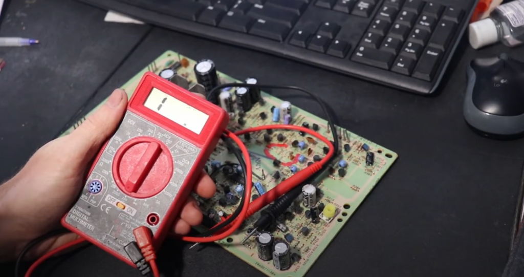
The ohmmeter must be turned on and calibrated. Take the resistor by its main part and put its leads to the probes without touching them. If you are measuring resistance in an existing circuit, turn off the power to that device.
The voltage of the battery installed in the ohmmeter is added to the voltage falling on the measured resistor of the working device – according to the law of the addition of voltages in the series connection of elements. As a result, the device “scales” to one side or the other, and you do not get a sane measurement. With tens of volts extinguished on the resistance to be measured, the arrow can be forcefully thrown back to either end of the scale. This can break the pointer as well as its spring and balancer.
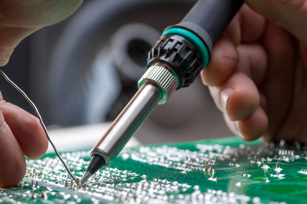
If the device’s circuit is complex – it contains electronic components containing diodes, transistors, and microcircuits, it is necessary to unsolder the resistor, the suitability of which is checked. The fact is that semiconductors, of which all these elements are made, also have a finite resistance of up to tens of ohms when current flows to one side. Be guided by the circuit diagram of the device being repaired. This requires a good knowledge of physics, electrical, and circuit engineering, without which you will not be allowed to repair electronics.
Digital ohmmeters (multimeters) have an electronic protection circuit and a fuse to protect the instrument from exposure to dangerous voltages. Such an ohmmeter can be damaged only by a voltage of hundreds or thousands of volts “breaking through” the device’s microcontroller. After such exposure, the multimeter cannot be restored. Be sure to disconnect power to the device where the resistor, coil, or motor winding is being evaluated.
Related Video:
Conclusion
How to measure resistance with an ohmmeter, and which type of instrument to choose? It depends on the measurement scheme and the application. An ohmmeter measures resistance between two leads.
If you still have questions, post your comments!
I was always fascinated by electricity and electronics as a kid. I would spend hours in my dad’s workshop, tinkering with any gadget I could get my hands on. So, when it came time to choose a career, it was no surprise that I decided to become an electrical engineer.
One of the most essential tools in any electrical engineer’s toolbox is an ohmmeter. An ohmmeter is used to measure the resistance of a circuit, and it is one of the first things we learn to use in our studies.
I remember the first time I used an ohmmeter in class. We were assigned to build a simple circuit, and then measure the resistance with our ohmmeters. I was so excited to finally be using this tool that I’d been reading about for years.
Thanks for sharing, Josh!