To understand how a circuit works, you need to know the action and purpose of each of the elements. This article will consider the principle of thyristor, the different types, modes of operation, characteristics, and types. We will try to explain everything as clearly as possible to understand even for beginners.
What is a Thyristor?
A thyristor is a semiconductor element that has only two states: “open” (current flows) and “closed” (no current). And both states are stable, i.e., the transition occurs only under certain conditions. The switching itself is very fast, though not instantaneous.
The way it works can be compared to a switch or a key, except that the thyristor switches with a voltage and is switched off by the loss of current or by removing the load. So it’s easy to understand how a thyristor works.
A thyristor usually has three outputs. One control and two through which current flows. You can try to describe the principle of operation briefly. When you put voltage to the control output, the circuit through the anode-collector is switched. So it is comparable with a transistor. The only difference is that the amount of current flowing in a transistor depends on the voltage applied to the control pin. A thyristor is either fully open or fully closed.
Basic Parameters of Thyristors
- Maximum allowable forward current. This is the maximum current value of an open thyristor. For powerful devices, it reaches hundreds of amperes.
- The maximum allowable reverse current.
- Forward voltage. This is the voltage drop at maximum current.
- Reverse voltage. This is the maximum permissible voltage across the thyristor in the closed state, at which the thyristor can operate without affecting its performance.
- Switch-on voltage. This is the minimum voltage applied to the anode. This refers to the minimum voltage at which the thyristor can operate at all.
- The minimum control electrode current. It is necessary to turn the thyristor on.
- The maximum allowable control current.
- The maximum permissible power dissipation.
There is also a dynamic parameter – the transition time from closed to open state. In some circuits, this is important. It can also specify the type of performance: by the time of opening or closing.
Appearance
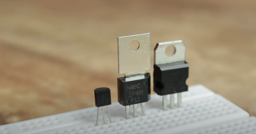
The thyristor appearance depends on the date of manufacture. Older thyristors are metal, “flying saucer” shaped with three leads. Two leads – cathode and control electrode – are on the “bottom” or “cover” (it depends on which side you look at it). And the control electrode is smaller in size. The anode can be on the opposite side of the cathode or stick out sideways from under the washer that is on the case.
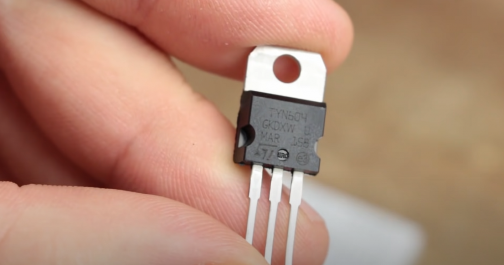
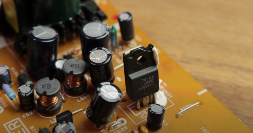
Modern thyristors look different. It is a small plastic rectangle with a metal plate on top and three leg pins on the bottom. The modern version has one inconvenience: it is necessary to look at which of the pins is the anode, where the cathode and the control electrode are. As a rule, the first is the anode, then the cathode, and the rightmost is the electrode. But this is, as a rule, that is, not always.
Thyristor Operation Principle in Simple Words
Let’s look at the principle of thyristor operation. The element’s starting state is closed. “The signal for switching to the “open” state is a voltage between the anode and the control pin. There are two ways to return thyristor to the “closed” state:
- remove the load;
- reduce current below the holding current (one of the specifications).
The thyristor is usually reset by the second option in circuits with alternating voltage. However, alternating current in a domestic circuit has a sinusoidal shape when its value approaches zero and resetting occurs. Therefore, it is necessary to either forcibly remove the power or remove the load in circuits powered by DC sources.
That is, the thyristor works differently in DC and AC voltage circuits. After a brief appearance of voltage between the anode and the control pin in a DC circuit, the element goes into the “open” state. Then there can be two possible developments:
- The “open” state holds even after the anode-control output voltage has disappeared. This is possible if the voltage applied to the anode control pin is higher than the non-latching voltage (this data is in the datasheet). This is because the current flow through the thyristor is stopped only by breaking the circuit or turning off the power supply. And the off/broken circuit can be very short-lived. So there is no current flow once the circuit is restored until the anode control pin is energized again.
- Once the voltage is removed (it is less than the cutoff voltage), the thyristor immediately goes into a “closed” state.
So in DC circuits, there are two ways to use a thyristor – with and without an open state hold. But more often, the first type is used – when it remains open.
The working principle of the thyristor in AC voltage circuits is different. The return to the locked state is “automatic” – when the current drops below the holding threshold. However, if the anode-cathode voltage is supplied continuously, we get current pulses at the thyristor output with a certain frequency. This is how switching power supplies are built. They use a thyristor to convert a sine wave into a pulse.
Testing Thyristor Functionality
You can check the thyristor with a multimeter or by making a simple test circuit. If you have the technical specifications in front of you, you can check the junction resistance simultaneously.
Multimeter Wiretapping
Let’s start with a multimeter wiretap. Set the device to the “Probing” mode.
Then we touch the probes to the pairs of leads one by one:
- When the probes are connected to the anode and cathode, the instrument should show an open circuit – “1” or “OL” depending on the multimeter. The thyristor is broken if other readings are displayed in at least one direction.
- There should be a small resistance in one direction between the anode and the control electrode (lead). In the opposite direction, it is breakage. If there is a breakage or a small resistance in both directions, the element is damaged.
Note that the resistance value varies from series to series – do not pay much attention to this. However, if you want to check the junction’s resistance as well, look at the specifications.
Thyristor Testing With a Light Bulb and DC Power Supply
If you don’t have a multimeter, you can test a thyristor with a light bulb and a power supply. Even an ordinary battery or any other DC voltage source will do. But the voltage must be sufficient to light the bulb. Another resistance or a normal piece of wire is needed.
- The plus from the power supply goes to the anode.
- Connect the bulb to the cathode. Its second lead to the minus of the power supply. The bulb does not light up because the thermistor is locked.
- Briefly (with a piece of wire or resistance) connect the anode and the control pin.
- The light bulb lights up and stays on, although the jumper is removed. The thermistor remains open.
- If you unscrew the bulb or turn off the power supply, the bulb will naturally go out.
- If the circuit/power supply is restored, it will not illuminate.

Along with the test, this circuit allows you to understand how the thyristor works.
Types of Thyristors and Their Special Features
Semiconductor technology is still being developed and improved. As a result, new varieties of thyristors have appeared over several decades, which have some differences.
- Dynistors or diode thyristors. They are different in that they have only two leads. They are opened by applying a high voltage to the anode and cathode in the form of a pulse. Also called “uncontrolled thyristors”.
- Trinistors or triode thyristors. They have a control electrode, but the control pulse can be applied:
– To the control output and the cathode. The name is cathode-controlled.
– To the control electrode and the anode. Correspondingly, anode control.
There are also different types of thyristors according to the locking method. In one case, reducing the anode current below the holding current is sufficient. A locking voltage is applied to the control electrode in the other case.
Thyristors by Conductivity
We said that thyristors only conduct current in one direction. There is no reverse conductivity. Such elements are called reverse-conductive, but there are more than that. There are other variants:
- Have a low reverse voltage, called reverse-conductive.
- Non-negligible reverse conductivity. Put in circuits where reverse voltage cannot occur.
- Triacs. Symmetrical thyristors. Conduct current in both directions.
Thyristors can operate in the key mode. When a control pulse arrives, they supply current to the load. The load, in this case, is calculated based on the open voltage. It is also necessary to consider the highest power dissipation. In this case, it is better to choose metal models in the form of a “flying saucer”. It is convenient to attach a radiator to them – for faster cooling.
Thyristors by Special Modes of Operation
We can also distinguish the following thyristor subtypes:
- Lockable and non-lockable. The principle of operation of a non-latching thyristor is slightly different. It is in the open state when plus is applied to the anode. The minus is on the cathode. It goes to the closed state when the polarity reverses.
- Fast-acting. Have a short transition time from one state to another.
- Pulsed. Transitions from one state to another very quickly, used in circuits with pulse modes of operation.
The main use of thyristors is as an electronic switch, serving to close and open an electric circuit. In general, many familiar devices are built on thyristors. For example, daisy chain running lights, rectifiers, pulse current sources, rectifiers, and many others.
Related Video: How Does a Thyristor Work?
Conclusion
A thyristor is not a full control switch. If there is a holding current, the thyristor remains in the open state, even if you stop applying a signal to the control junction.
Thank you for reading this article. If you still have questions, write your comments!