
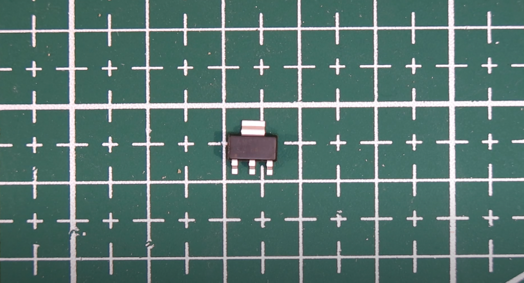
Radio amateurs and educational institutions often use this type of transistor because the characteristics of the BC547 bipolar NPN transistor allow it to be used in various electronic devices. It comes primarily in TO-92 or advanced TO-226 packaging. The maximum output current this semiconductor can handle is 100mA.
It also has excellent gain (up to 800 hFE) and low noise (up to 10 dB), making it ideal for primary signal amplification stages. Its ability to operate in the 300 MHz band allows it to be called high-frequency. Typical saturation voltage is only 90 mV, which is a definite advantage when used in circuits as a switch.
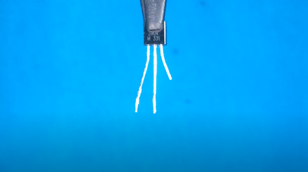
BC547 Pinout
BC547 first appeared on the market of electronic radio components in April 1966, thanks to Philips (Holland) and Mullard (UK). It was a joint development of the then-popular BC107. It was identical in its technical characteristics but was produced unlike the metal bc107 in a plastic sealed housing TO-92. It is currently the current replacement for the older BC107 or BC147, which are included in many developments by Mullard and Philips.
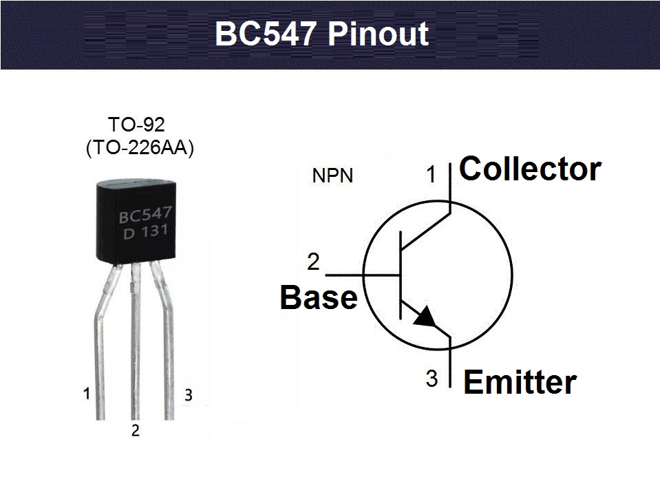
The TO-92 (or TO-226AA) package pinout of the BC547 has three flexible pins for hole mounting. If you look at the bevel from the front, the purpose of these pins is from left to right: collector, base, emitter. The figure shows the basic appearance of the device, which will vary slightly depending on the particular brand, but the characteristics and pin assignments remain identical.
BC547 Basic Specifications
The datasheet for the BC547 usually describes similar transistors: BC546, BC548, BC549, and BC550. Similar, but not exactly. They do differ from each other. For example, the BC547 differs in the threshold voltages and is between the BC546 and the BC548. Also, all types of devices are divided into groups of maximum current amplification factor hFE- from A to C. Group “A” will have the smallest gain, and “C” will have the largest gain.
BC547, BC548, BC549 are identical transistors created on the same production line. During their testing process just before release, I classified them as -7, -8, or -9 based on VBCO and VCEO measurements and noise components.
A detailed description can be found in the datasheet from the manufacturer. It usually includes a table of maximum allowable operating parameters and electrical characteristics at which the device operates stably.
Maximum Permissible Parameters
The manufacturer states the maximum permissible values of the operating parameters at the beginning of the technical description. They include the following parameters:
- VCEO – indicates the maximum potential difference applied between the collector-emitter contacts. For example, the BC547 cannot hold more than 45 volts, so this value is specified as the safe operating voltage that must be applied to the collector load.
- IC (max) is the maximum collector current that can be applied across the collector-emitter pins. The BC547 should not be more than 100mA because this value will be the breakdown limit, above which the device will surely burn out. So you can see that it starts to heat up well even before reaching this limit, already at 60 mA. Therefore, it is recommended to use it at values less than half of IC (max).
- PC (max) is the maximum power of the devices or the nominal load that can be connected through its collector-emitter. This value is quite consistent with, and interrelated to, IC(max) and is 500 mW or half a watt for the entire group.
The addition “max”, in the parameter limits, indicates the maximum values, but sometimes it is omitted from the description. The following is a complete list of BC547 operating limits taken from Fairchild Semiconductor’s datasheet.
Electrical Characteristics
Now let’s look at the electrical parameters of the BC547. The device manufacturer specifies them right after the description of the limit values. A separate column (test condition) indicates the values at which the manufacturer tested the device in these characteristics. Usually, the tests are performed at an ambient temperature of 77 degrees Fahrenheit (25 degrees Celsius) or less.
Gain
The BC547 has a fairly large current amplification factor (hFE). For example, group “C”, according to the hFE U classification, starts at 420 and ends at 800. These values are essential for a bipolar and are one of the first criteria for its selection. A higher hFE level simply assigns more sensitivity to a particular device, which means that it can start at the lowest base currents but still switch heavier loads through its collector.
The Complementary Pair
A low-noise transistor designed to amplify weak high-frequency signals almost always has a complementary pair with a different conductivity type and a similar hFE gain. This is due to the widespread use of such devices in the primary amplification stages in the pair. The complementary pair with the PNP structure for it is BC557.
BC547 Alternatives
A complete modern equivalent of BC547 is BC550. Also, before looking for analogs, it is recommended to look closely at their neighbors in the datasheet, which have only minor differences in breakdown voltage thresholds: BC546, BC548, BC549. Some radio amateurs use 2N3904, 2N4401, BC337, BC639, 2N3055, 2N2369, 2SC5200 as replacements.
Another one of the most common substitutes is the 2N2222 transistor. It has similar characteristics, including pinout and housing. The only differences are higher power dissipation (up to 625 mW), collector current up to 600 mA, and slightly increased input and output capacitances. The input and output capacitances can only affect the circuits during high-frequency operation. So, if more gain is needed, the 2N2222 can be used.
Labeling
Philips developed the BC547 in 1966 in Holland, so it is labeled according to the European Pro Electron system. The first letter indicates the type of semiconductor used – “B” for silicon. The second letter indicates the frequency of operation – “C” low-power, low-frequency. So even though it is high-frequency (up to 300 MHz), the manufacturer, for some reason, indicated it in the marking as low-frequency. Unfortunately, history is silent about the reasons for this designation. Sometimes, they don’t write the first letter in the designation, so you get C547B, C547C, C547C, C547B.
A Little About Standards
Manufacturers are constantly improving the manufacturing process and can change the specified specifications, but they must not be less than the values registered for bc457 in the Pro Electron standard. For example, semiconductors have a maximum power of 625 mW, which is currently the most common. At Philips, the hFE gain for group “B” ranges from 220 to 475. In addition, some manufacturers have appeared to support pulsed collector current (up to 200 mA). Therefore, please reread the datasheet before using the device in your projects.
How it Works
When the input voltage is applied to the terminals, some current (IB) flows from the base to the emitter and drives the current to the collector (IC). Therefore, the voltage between base and emitter (VBE) for an NPN structure must be direct. A positive potential is applied to the base, and a negative potential is applied to the emitter. The polarity of the voltage applied to each pin is shown in the figure below.
The input signal is amplified at the base and then transferred to the emitter. Less current in the base is used to drive more between the collector and emitter (IC).
Transistors of the n-p-n structure are sometimes called reverse conducting semiconductor devices.
When the transistor is open, it can pass IC up to 100 mA. This stage is called the saturation region. At this stage, the allowable voltage between collector and emitter (VBE) can be about 200 mV, and the VBE can reach 900 mV. When the base current stops flowing, the transistor shuts down completely, this stage is called the cutoff region, and the VBE will be about 650 mV.
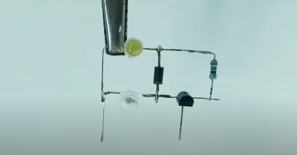
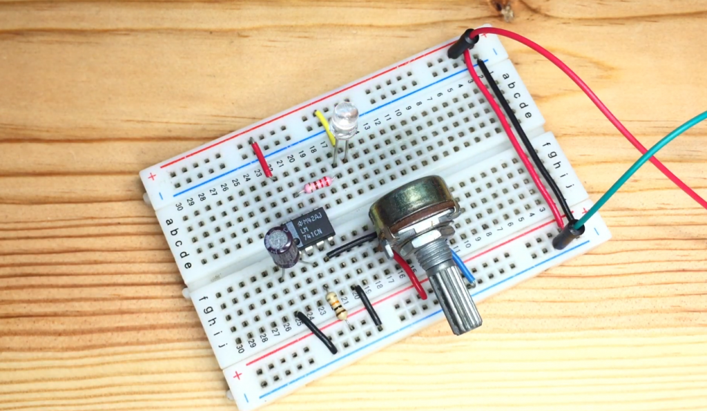
Application
Widely used in keying and amplifying mode, in various control circuits of relay drivers, LEDs, motors, as well as schemes of low and high-frequency signals amplification. Examples of circuits and how to create simple devices by a hinged mounting can be seen in the video. In addition, in this video, you can find information about how to use bc547 in some projects: delayed turn off with your own hands, automatic lighting, LED strobe light, simple burglar alarm, and audio amplifier.
Related Video: 10+ Single BC547 Transistor Projects for Beginners
Manufacturers
Companies such as NXP, Philips, Micro Electronics, Fairchild, ON Semiconductor, Vishay, and many others are leaders in manufacturing this device.

I’m no expert on transistors, but I decided to give the BC547 a try in my latest project. I was surprised at how easy it was to use. The transistor worked great and I had no problems with it. Overall, I was very pleased with the BC547 transistor and would definitely recommend it to anyone looking for an easy-to-use transistor.
How to reduce current / voltage to base of transistor 12 to 5 volt
To reduce the current voltage from 12 to 5 volts, you can use a voltage regulator or an adjustable voltage divider circuit. Both of these methods will help you adjust the current voltage to the desired level. Additionally, you can use a resistor-capacitor filter or an inductor-capacitor filter to reduce the voltage further.