

Arduino Nano is one of the three most popular Arduino boards. It allows you to create compact devices that use the same controller as the Arduino Uno. The name of the board nano speaks for itself – it really has small dimensions with the same functionality. This article will take a closer look at the board: we will look at the board’s pinout, learn about the connection features, and make a short overview of the shields and extension boards.
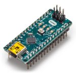 Arduino Nano is a small, full-featured debug board adapted for use with breadboards, based on the ATmega328 (Arduino Nano 3. x) or Atmega168 (Arduino Nano 2. x) microcontroller.
Arduino Nano board: a quick overview
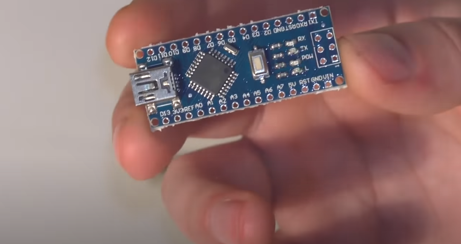
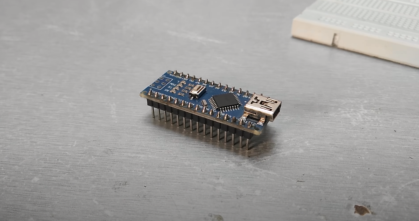
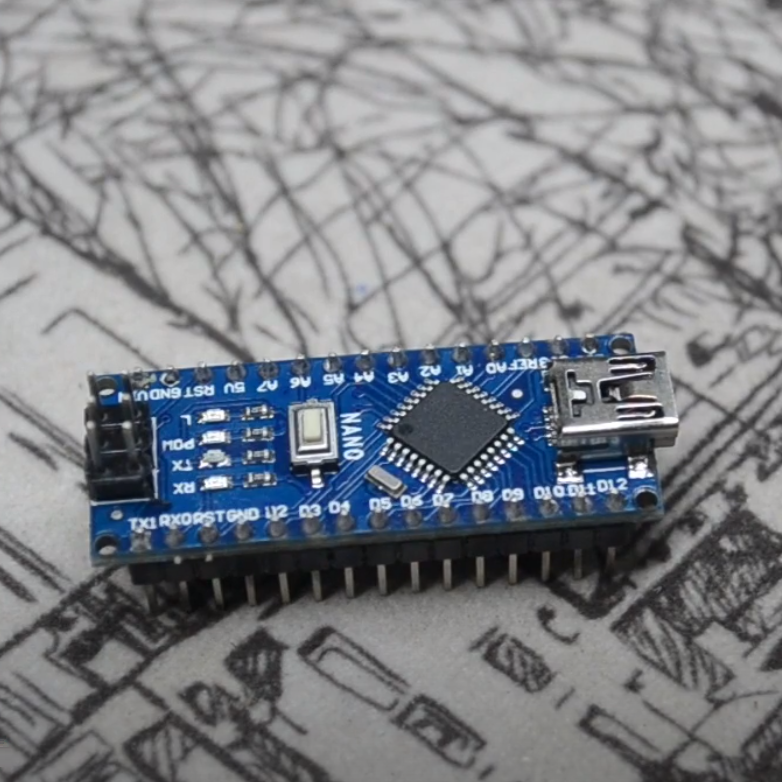
Arduino Nano V3Nano is one of the smallest Arduino boards. It is a full analog of Arduino Uno – also works on the chip ATmega328P (although you can still find options with ATmega168), but with a smaller form factor. Due to its size, the board is often used in projects where compactness is important. The board does not have an external power socket. Arduino works via USB (mini-USB or micro-USB). Otherwise, the parameters are the same as the Arduino Uno model.
Technical specifications of the Arduino Nano:
- The power supply voltage is 5V;
- Input power supply 7-12V (recommended);
- Number of digital pins – 14, 6 of them can be used as PWM outputs;
- 8 analog inputs;
- The maximum current of the digital output is 40 mA;
- Flash memory 16 KB or 32 KB, depending on the chip;
- 1 KB or 2 KB RAM, depending on the chip;
- EEPROM 512 bytes or 1 KB;
- 16 MHz frequency;
- Dimensions 19 x 42 mm;
- Weight 7 g.
The board can be powered in two ways:
- Via mini-USB or micro-USB when connected to a computer;
- Through an external power supply with a 6-20V low ripple voltage.
The external power supply is stabilized with the LM1117IMPX-5.0 5V circuit. When connected via a cable from a computer, a connection to the stabilizer is made via the Schottky diode. The diagrams of both types of power supply are shown in the picture.
At connection of two voltage sources, the board chooses the one with the highest power supply.
The Arduino Nano board has the same voltage and current limits for the board inputs and outputs. All digital and analog contacts work in the range from 0 to 5 V. When power is supplied beyond these values, protective diodes will limit the voltage. In this case, the signal must be connected through a resistor in order not to disable the controller. The highest inrush or outrush current should not exceed 40 mA, and the total contact current should not exceed 200 mA.
There are 4 LEDs on the board which show the signal state. They are designated as TX, RX, PWR and L. The first two LEDs light up when the signal level is low and indicate that a TX or RX signal is active. The PWR LED lights up when the voltage is 5V and indicates that power is connected. The last general-purpose LED lights up when a high signal is given.
At the moment, there are several types of Arduino Nano. There are versions 2.X, 3.0., which differ only in the chip on which they work. Version 2.X. uses a chip ATmega168 with less memory (flash, non-volatile) and lower clock frequency, version 3.0. runs on a chip ATmega328.
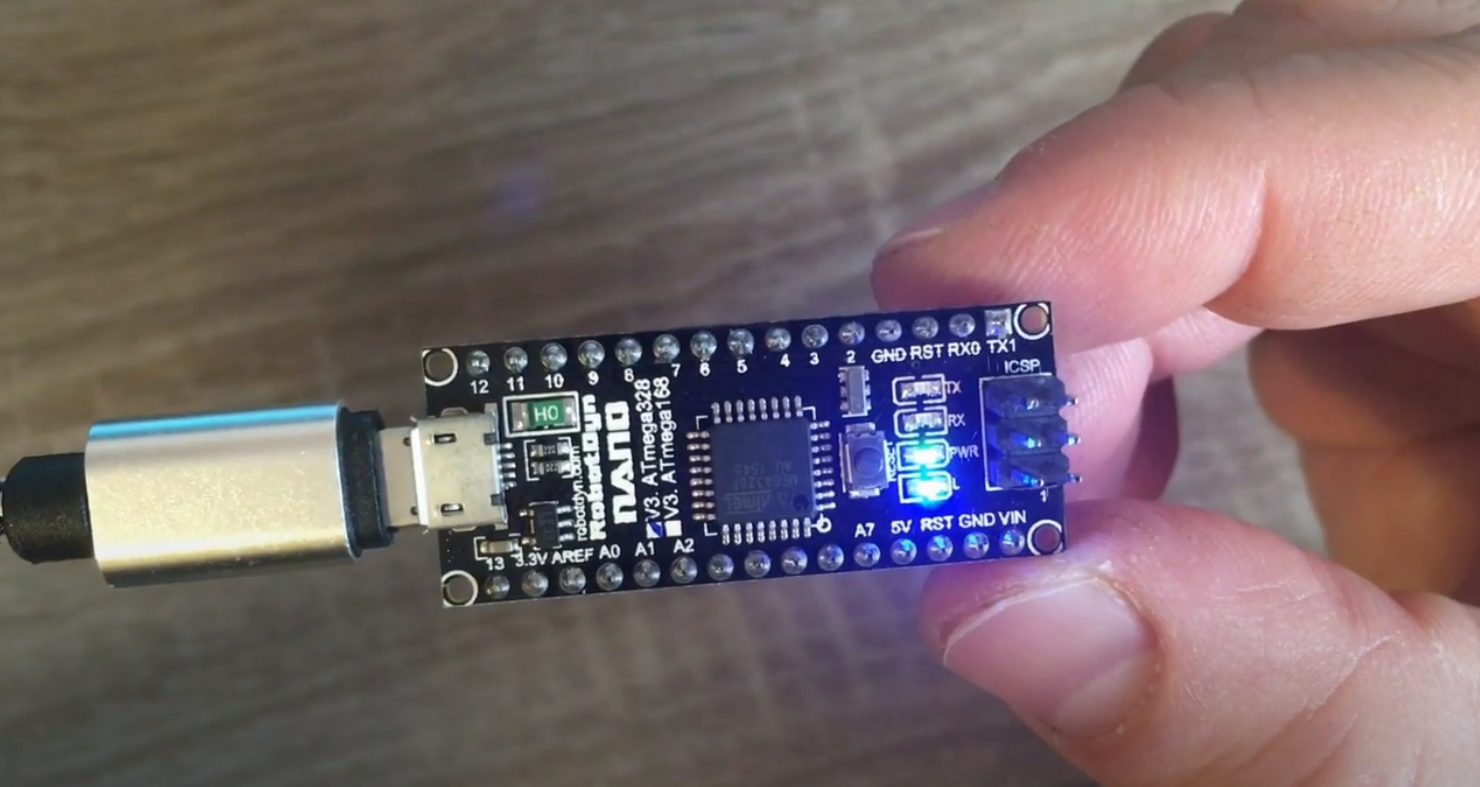
Arduino Nano Pinout
Arduino Nano board has 14 digital contacts, which are marked with the letter D (digital). The contacts are used as inputs and outputs; each of them has a pull-up resistor.
The analog pins are marked with the letter A and are used as inputs. They do not have pull-down resistors; they measure the voltage applied to them and return the value using the analogRead() function.
On some digital pins, you can see the ~ symbol. These pins can be used as PWM outputs. Arduino nano is equipped with six such pins: D3, D5, D6, D9, D10, D11. The analogWrite() function is used to work with PWM outputs.
Arduino Nano Pins Description
- Digital I/O: D0-D13.
- Analog inputs/outputs: A0-A7 (10-bit ADC).
- PWM: Pins 3, 5, 6, 9, 10, 11.
- UART: D0 and D1 (TX and RX, accordingly).
- I2C: SDA – A4, SCL -A5.
- SPI: MOSI – 11, MISO – 12, SCK – 13, SS(10).
Let’s run through the pins:
- 0 – TX (UART data transmission), D0.
- 1 – RX (UART data reception), D1. RX and TX can be used for serial communication or as regular data ports.
- 3, 29 – reset.
- 4, 29 – grounding.
- 5 – D2, interrupt INT0.
- 6 – D3, interrupt INT1 / PWM / AIN0.
- 7 – A4, counter T0 / I2C SDA / AIN1. AIN0 and AIN1 are inputs for a fast analog comparator.
- 8 – A5, counter T1 / I2C SCL / PWM bus.
- 9 – 16 – D6-D13 ports, of which D6 (9), D9 (12), D10 (13) and D11 (14) are used as PWM outputs. D13 (16 pins) is an LED. D10 – SS, D11 – MOSI, D12 – MISO, D13 – SCK are also used for SPI communication.
- 18 – AREF is a reference voltage for the ADC microcontroller.
- 19 – 26: analog inputs A0… A7. The ADC capacity is 10 bits. A4 (SDA), A5 (SCL) – are used for communication via the I2C bus. To create using a special library Wire.
Microcontrollers have a lot of functionality, but they have one drawback – it’s a limited number of pins in the battle with the Arduino Mega. Therefore, you should consider how to simplify the design as much as possible to reduce the number of contacts needed to connect the device at the schematic stage.
Connecting the Arduino Nano
Connecting the Arduino Nano board to your computer is not very difficult – it is similar to a regular Uno board. The only difficulty may arise when working with a board based on the chip ATMEGA 168 – in the settings, you need to select first board Nano, and then the desired option processor.
Installing the Driver for CH340
The CH340 chip is often used in Arduino boards with a built-in USB-to-Serial converter. It allows you to reduce the cost of board production without affecting its performance. With this programmer, you can easily flush Arduino boards. To start working with this chip, you need to install the driver on your computer.
Installation is performed in several stages:
- Download the archive with the driver for the required operating system (Windows, macOS and Linux).
- Unpacking the archive.
- Search for the SETUP.EXE file, launch it.
- A window will appear on your monitor where you should press the Install button. Installation of the driver will start, after which you can start working with the schematic.
Setting Up the Arduino IDE
The Arduino IDE standard development environment is used to work with all kinds of Arduino computers. To start working, you must first download the Arduino IDE from the official website and install it. It is more convenient to download Windows Installer, especially if the IDE is installed on a permanent work computer. If you downloaded the archive, you need to unpack it and run the Arduino.exe file.
Once the environment is installed, you should run it. To do this, you need to connect the Arduino board itself to your computer via USB. Then go to Start menu >> Control Panel >> Device Manager, find there the COM and LPT ports. In the list, you will see the installed board and the port number to which the board is connected.
After that, you need to run the Arduino IDE, go to Tools >> Port and specify the port to which the Arduino is connected. In Tools >> Boards, you need to select the model of the connected board, in this case, the Arduino Nano. If you have a Nano board version 2.0, you also need to select the CPU option in the corresponding menu.
It is important to remember that if another board connects to your computer, you will need to change the settings again to the appropriate device.
Examples of Projects with Arduino Nano
There are a lot of projects using the Nano board. Ideally, in any Arduino Uno project, you can easily add a Nano board and do not have to change anything in the code. That’s why often, after debugging a project on the “big and convenient” Uno, the scheme is converted to nano and used in the working version of the “reduced” controller, which is easier to make miniature.
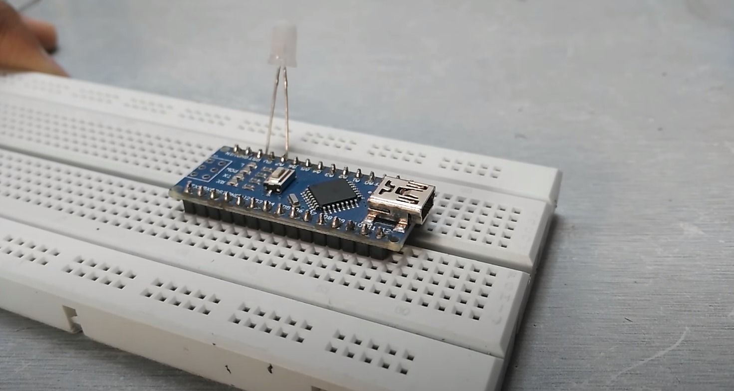
Connecting LEDs to Arduino Nano
Flashing LED can be used as a test program to check the board operation. The board has a built-in LED L on it, and usually, the first projects are performed with it. However, you can also connect an external LED to the D13 output. Of course, we do not forget that you have to connect the LED through a resistor to avoid burning it and damaging the board. The anode of the LED is connected to the resistor, which is connected to the D13 output. The cathode of the LED is to the ground. Here is an example circuit:
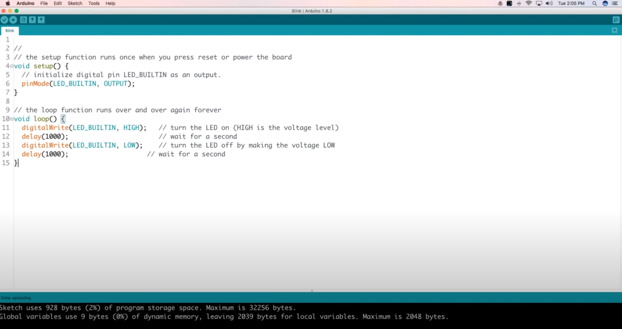
In the Arduino IDE, there is an example that enables the flashing of an LED. To do this, you have to go to File >> Examples >> 01. Basics >> Blink and load the example. After unloading the file Arduino will run the program, flashing the LED once per second.
Connecting LCD 1602 to Arduino Nano
LCD 1602 screen is quite common, there are various types of shields for it, but you can also connect it directly to the Arduino. To connect the display to the board, you need Arduino Nano, a breadboard, LCD 1602 screen and connecting wires.
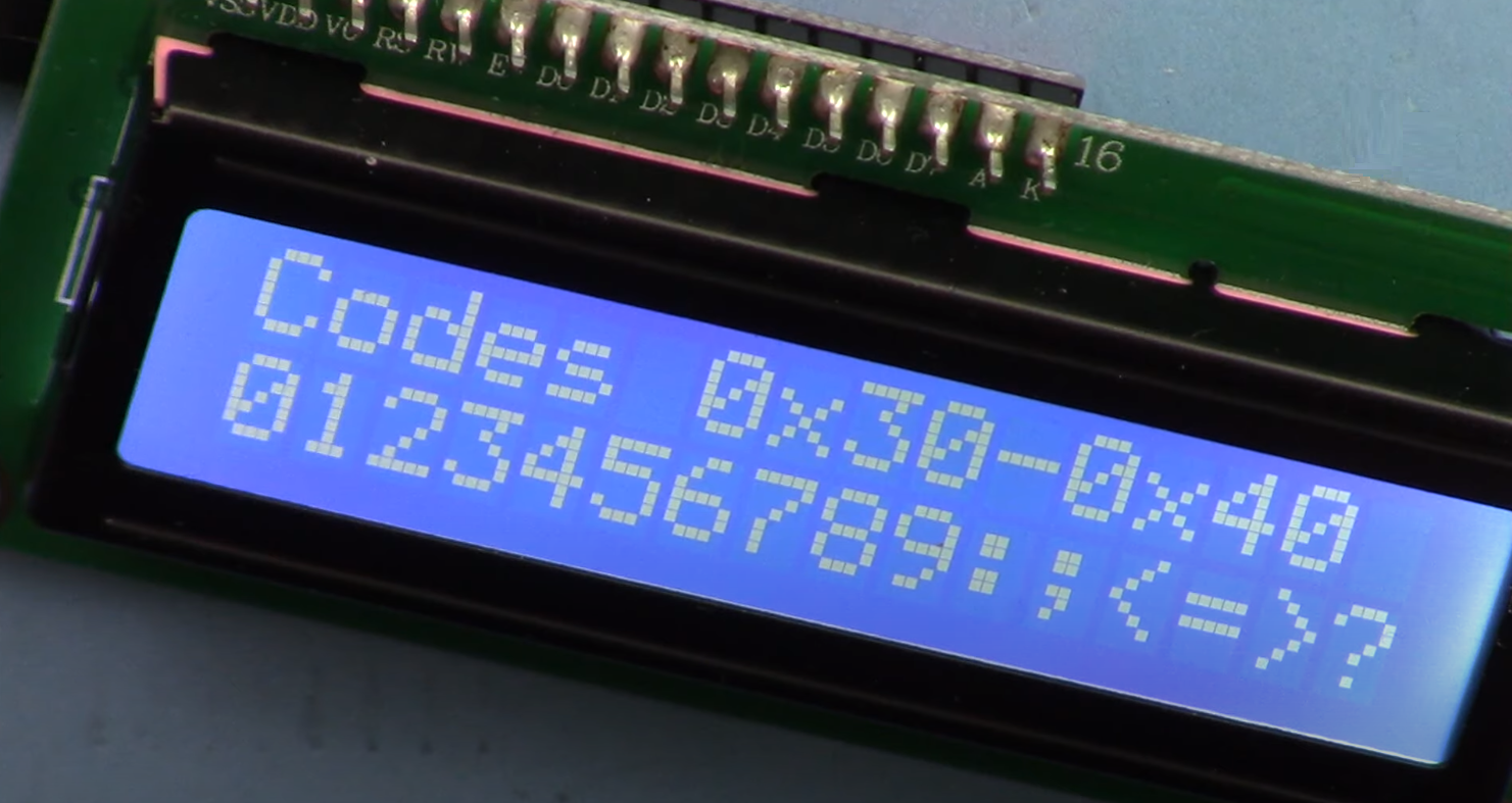
The choice of pins to which to connect the display can be any. For example, the following configuration will be chosen: contact RW from the display is connected to the ground, the 4th pin of the display – to A0 on the Arduino, 6th pin – to E (Enable), from 11 to 14 pin are connected to the D4-D7. The screen is connected. In order to write the code, you need to connect the LiquidCrystal library. There is also a test sketch in it that allows you to check if the installation is working. The code can be found at Arduino \ libraries \ LiquidCrystal \ examples \ HelloWorld.ino. In the sketch, you only need to change the contact numbers to which the screen is connected. If everything is connected correctly, the message on the monitor will light up.
Connecting nRF24L01 to Arduino Nano
Radio module nRF24L01 is used in cases when it is necessary to receive data from sensors, which are located at a distance from the control device. The module is easy to use and easily connects to the Arduino.
Connection to the Arduino Nano is shown in the picture. The ground from the board is connected to the module ground; the voltage is 3.3V, the 3rd contact (CE) is connected to D9, the 4th to 7th contact is connected to D10-D12. For the 3rd and 4th pins, you can use any pin. The main thing is to specify it later in the code.
A capacitor between the ground and power outputs can also be soldered to the radio module, which will reduce noise and make the device more stable.
There are several libraries for working with the module. The most common libraries are RF24 and Mirf. The choice of one or another library is determined by its usability.
Popular Shields for Arduino Nano
Extension cards (or Arduino shields) are used to solve various tasks and simplify projects. All necessary electronic components are installed on the extension board, and interaction with other controllers is carried out through standard Arduino contacts.
Nano Uno shield is a shield that allows turning a Nano board into an Uno. The platform has various connection blocks, a reset button and a power slot.
Arduino Nano Ethernet Shield – is used to provide working with the network over Ethernet. It is similar to the Arduino Uno Shield but is smaller and much more convenient in real projects.
Arduino Nano Motor Shield is a shield used in robotic projects for connecting motors and motors to an Arduino board. Its main task is to provide control of devices that consume high (in comparison with Arduino) current. It is also possible to control the motor power and change its direction of rotation with the help of the keypad. There are many models of Motor Shield boards. In the circuit, all have a powerful transistor, heat dissipation components, a circuit for connecting an external voltage source and connectors for connecting motors.
Arduino Nano Sensor Shield is the most common platform. The shield is simple – his main task is to provide a convenient connection to other devices’ Arduino board. There are additional power and ground connectors on the shield, connectors for connecting an external voltage source, LED, and reset button.
Arduino Data Logging Shield – shield, which allows you to write a log of data from sensors. It is also used as file storage or real-time clock. To work with the shield, you have to use a special library that allows you to log information to a memory card.
Arduino Proto Shield is a platform for quick prototyping or creating your own shield. There are platforms for mounting the necessary components on these boards, a reset button, 2 LEDs, and an external power connector. With their help, you can increase the compactness of the device.
FAQ
Is Arduino Nano 3.3 v or 5V?
Arduino Nano comes with 3.3V and 2 x 5V power input pins, of which the one labeled as VIN is for all the 5V power supplies. The Arduino Nano can be powered by either 3.3 volts or 5 volts, depending on what voltage source you use to power it.
How many pins Arduino Nano?
The Arduino Nano has 14 digital pins (of which 6 can be used as PWM outputs).
Can Arduino Nano run on 3V?
The Arduino Nano can run on 3V. It is a low-power microcontroller board with a USB interface. The Arduino Nano contains all the circuitry necessary to support the microcontroller, providing direct access to GPIO pins and memory and supplying power for both the board’s internal operations and for external devices.
Can Arduino Nano run on 9V?
The Arduino Nano can run on 9V. Cut the metal barrel at the end of your 9V battery snap so that both wires are still showing.
Conclusion
Arduino Nano controllers are actively used in various DIY projects. Using a miniature controller allows you to create devices in a small form factor, which is important for projects in the field of automation and robotics. This board is quite compact, convenient and has all the features of “big Uno”. You can recommend it to use even for beginners.


Is it possible to make a device that would work like this, would trigger a voice message like “Volume threshold exceeded!!!” when the sound is loud?
It is possible to make a device. For this project on the Arduino Nano, you need a sound sensor and a df player mini to play the voice message.