
Arduino Leonardo is a platform based on the ATmega32u4 microcontroller. With this board, you can create projects where the Arduino device actively interacts with the computer and acts as a familiar peripheral – mice, keyboards, and game controllers. In contrast to the well-known board Uno, this model has a number of features. In this article, we will learn what they are. You can find a description of the characteristics, pinout, and connection features to the Arduino IDE.
Description of the Arduino Leonardo Board
The Arduino platform allows you to create a wide variety of autonomous devices, but when you connect traditional boards Uno, Nano, Mega, it was impossible to make them work as usual peripherals – for example, mice or keyboards. You can’t just connect a regular joystick through the Arduino Uno to the computer and control it. For example, the cursor – you have to install an application on the computer itself, which will interpret the codes from the serial port and set the cursor in the right place.
The Arduino Leonardo board greatly expands the possibilities for connecting Arduino to the computer. It is treated by the computer as a standard HID device and can directly send the desired control signals. We can’t say that this board can replace Uno, but it can become the basis for new, very interesting, and unusual projects with its unique features.
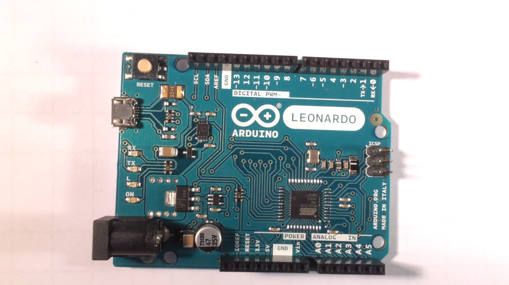
At the core of Leonardo is a quite advanced ATmega32u4 microcontroller. The board itself looks pretty much like Uno. You can find two dozen inputs and outputs, a micro-USB connector, a reset button as well as ICSP connectors, and power input. The board’s power supply is standard for Arduino, with a recommended voltage of 7-12 volts.
The number of digital inputs and outputs is 20, and the analog inputs are 12. To the usual analog pins A0-A5, here are added more pins 4,6,8, 9,10, 12 connected to the ADC. The embedded flash-memory has a capacity of 32 KB, four of which are dedicated to the loader. The RAM is 2.5 KB, and the clock frequency is 16 MHz.
Features of the Arduino Leonardo board (some of them are common to all ATMega microcontroller-based devices):
- Possibility of direct connection, from an external power supply or via USB. Power selection is automatic. The platform works with a voltage from 6 to 20 volts.
- Programming is done using the Arduino Leonardo driver. The microcontroller at the heart of the device comes already with a bootloader, which simplifies software installation. The AVR109 protocol is used for communication.
- Automatic rebooting is provided (no need to press an additional button). The process is started by opening a virtual CDC COM port at a 1200 baud rate. After that, the system is rebooted. If desired, the process can be activated manually with a special Reset button. At power-up, the controller immediately works with the installed software.
- A fuse is provided in the device to provide protection against excessive overcurrents and short circuits in the system. Despite the presence of such an option in all PCs, additional reliability is not superfluous. The fuse link blows when a current greater than 0.5 Amps is flowing. The circuit is broken until normal operation is restored.
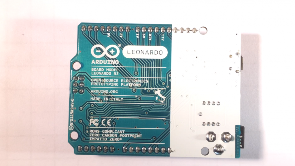
- The Arduino Leonardo board has the standard dimensions of the Uno – only 3.23 by 2.36 inches. Only the power connector is outside the boundaries of the device. The distance between the seventh and eighth pins is 4 mm, and the rest is 2.5 mm.
On the whole, the board looks quite traditional, but the board connectors deserve special attention, on which we will dwell in detail.
Diagram and Pinout
Before connecting, it is important to present the Arduino Leonardo’s pinout and understand the intricacies of connection.
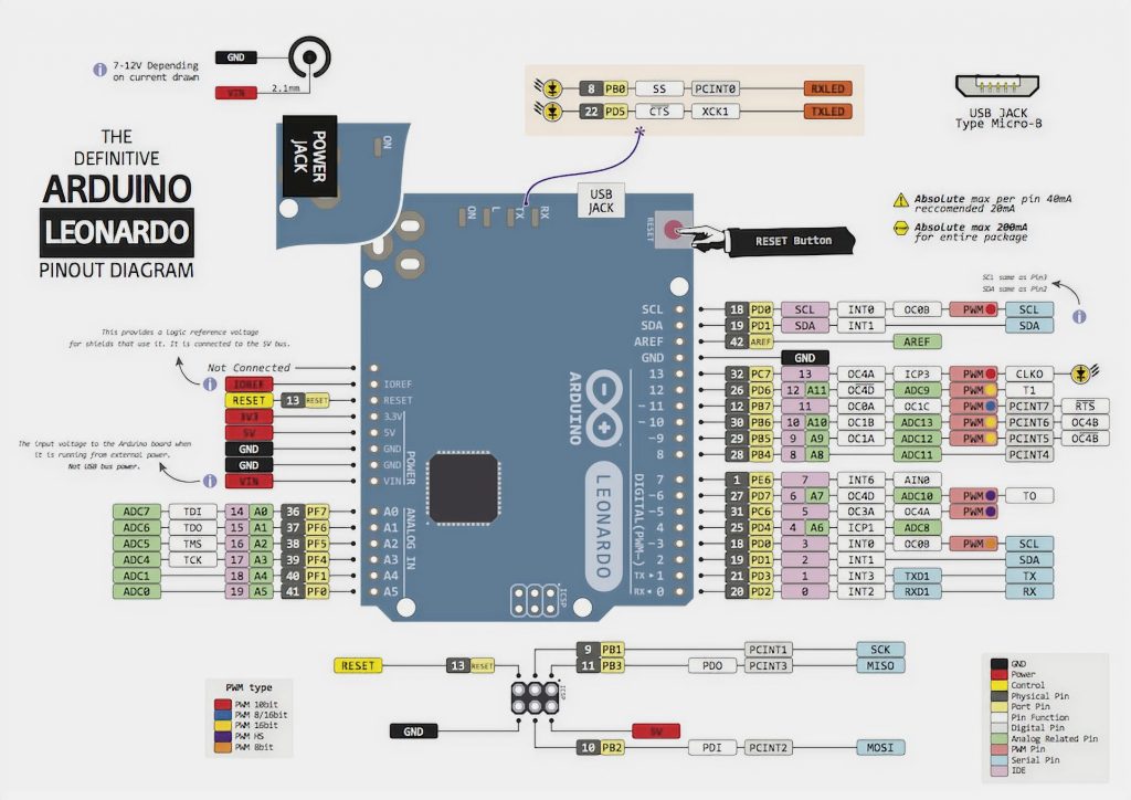
Powering PINs:
- VIN – supplying voltage from an external power supply. This input has no connection to the five volt USB connector or other stabilization voltage. External power can be supplied to the PINs when an external power supply is connected to the controller.
- 5V is the socket to supply five volts from the stabilizer on the board. The voltage is used for the microcontroller. Do not use this input to power the unit directly. This approach can damage the board in case of voltage surges (connecting a stabilizer can solve this issue).
- 3.3V – voltage from the regulator. The upper limit of the operating current is 0,05 A.
- IOREF. The task of the PIN is to decode the voltage information of the ATmega32u4. Depending on this parameter, the board switches to a more suitable power supply, or a level converter is applied. In the last case, a 5 or 3.3-volt power supply is opened.
PIN input and output:
- Digital PINs (from 0-13). The logic level for “zero” is 0 volts and for “one” is 5 volts. There are pull-up resistors that are disabled by default but can be enabled if needed.
- Pins with connection to the ADC (A0-A5, A6-A11). These inputs are analog, but they can also be used in digital mode. The default voltage is from 0 to 5 volts.
- PWM – PINs named “three”, “five”, “six”, “nine”, “ten”, “eleven” and “thirteen”. An 8 bit resolution is available using the analogWrite function.
- The SPI is the PIN of the ICSP connector. A special feature of the Arduino Leonardo board is that there is no wiring between the digital inputs and outputs (previously, this approach was used). If the board does not have an ICSP connector with six pins, the product will not work.
- UART – PIN 0 (RX) and 1 (TX) to receive and transmit information, respectively. It is used to connect to other devices using the Serial1 class. If the controller is powered via USB from a computer, the Serial class is used.
- TWI/I2C. This PIN is used for interaction with peripheral devices using the asynchronous protocol. The connection is made with two wires using the Wire library.
On the Arduino Leonardo R3 board, there is a group of LEDs, by which you can judge whether the device is working or not:
- RX and TX are the LEDs that blink while information is being transmitted between the computer and the controller.
- L (for PIN 13). It turns on when the parameter HIGH is sent and turns off when LOW.
- ON is the LED indicating that the Arduino Leonardo board is powered.
Additional connectors include micro-USB, a connector for external power supply from 7 to 12 volts, as well as ICSP connector. The latter is used for programming the microcontroller.
Connection and Firmware of the Arduino Leonardo
Connecting the device requires a USB cable connected to a PC or a power supply from an external source. This can be a remote battery or an AC/DC type adapter. This solution made the controller cheaper to produce and increased the flexibility to use with a PC.
When installing the Arduino Leonardo driver, you need to proceed as follows:
- connecting the device to the PC;
- Waiting for the start of the software installation wizard (if there is no start, manually go to the hardware section, select the Arduino Leonardo line, and press update);
- searching for the drivers on the PC and clicking “Next”;
- In the folder with the software, select the required driver;
- accepting the installation.
To flash the device, it is enough to press the Upload button to load the software into the memory of the device automatically. Then, the controller’s reset is initiated, which leads to the bootloader start (responsible for receiving, saving, and starting the new software). Unlike other models here, after the automatic reset, the platform waits for a new serial port. Then the sketch is sent to the newly created COM port. If the auto-reset does not activate for some reason, you need to do the following:
- Pressing the reset button and holding it down until the word Uploading appears;
- control the bootloader startup (the system should see the new port).
These actions are necessary if the standard firmware system did not work.
Comparison with Arduino Uno, Nano, Mega
Unlike its predecessors, the Arduino Leonardo board runs on just one chip. It has an independent USB connector. It is based on the ATmega32u4 microcontroller, which has more functionality compared to the Mega, Nano, and Uno.
Other differences:
- Due to the lack of a separate chip for serial communication processing, the serial ports are virtual in nature;
- no automatic restart is triggered when the serial port is opened on the PC;
- the device can be detected by the PC as a serial port, mouse, keyboard, or HID device.
The Leonardo model has more RAM, more PWM inputs. But the main change is the ability to connect the device via a USB connector, which significantly increased the platform’s connectivity and functionality.


