
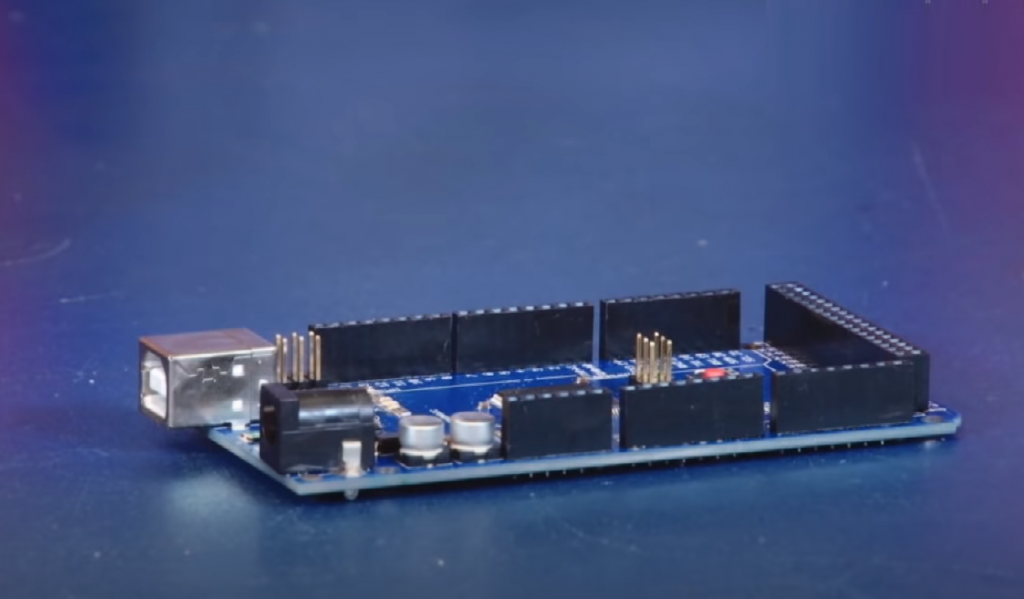
Arduino Mega 2560 is the flagman platform for development based on the ATmega2560 microcontroller.
The board has everything you need for convenient microcontroller operation: 54 digital inputs/outputs, 16 analog inputs, USB programming slot, external power slot, and reset button.
Connecting and Configuring
To launch the platform, download and install the Arduino IDE integrated development environment on your computer.
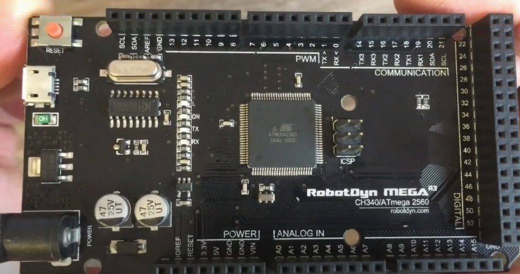
Board Elements
ATmega2560 Microcontroller
The heart of the Arduino Mega platform is an 8-bit AVR family microcontroller – ATmega2560 with 16 MHz clock speed. The controller provides 256KB of Flash memory for storing firmware, 8KB of SRAM, and 4KB of non-volatile EEPROM memory for data storage.
It should be noted that with a power supply voltage of 7-20 volts, the board works perfectly, and with a smaller, for example, 5 volts, there may be situations with the unstable operation. Take note of this.
ATmega16U2 Microcontroller
Microcontroller ATmega16U2 provides a connection of microcontroller ATmega2560 with the USB port of the computer. When connected to a PC, the Arduino Mega 2560 is defined as a virtual COM port.
| LED Name | Destination | |||
|---|---|---|---|---|
| RX and TX | Flash when exchanging data between Arduino Mega 2560 and PC. | |||
| L | User LED connected to the 13 pin microcontroller. At high level, the LED turns on, at low level, the LED turns off. | . | ||
| ON | Arduino Mega Nutrition available. |
USB Connector
Type-B USB connector for power and firmware of the Arduino Mega 2560 platform using a computer.
External Power Connector
It’s a connector for an external power supply from 7V to 12V.
Reset Button
It’s an analog of the RESET button on a regular computer. It is used to reset the microcontroller.
5V Voltage Regulator
Linear voltage regulator LD1117S50CTR with 5-volt output provides power for microcontrollers ATmega2560, ATmega16U2, and other platform logic. The maximum output current is 800mA.
3.3V Voltage Regulator
It’s a linear voltage regulator LP2985-33DBVR with 3.3-volt output. The line is only output on a 3V3 pin. The maximum output current is 150mA.
ICSP Connector
ICSP-connector is designed for in-circuit programming microcontroller ATmega2560. Also, using the SPI library, these outputs can communicate with the expansion boards on the SPI interface. SPI lines are output on a 6-pin connector, as well as duplicated on digital pins 50 (MISO), 51 (MOSI), 52 (SCK), and 53 (SS).
ICSP1 Connector
It’s an ICSP-connector for internal microcontroller programming ATmega16U2.
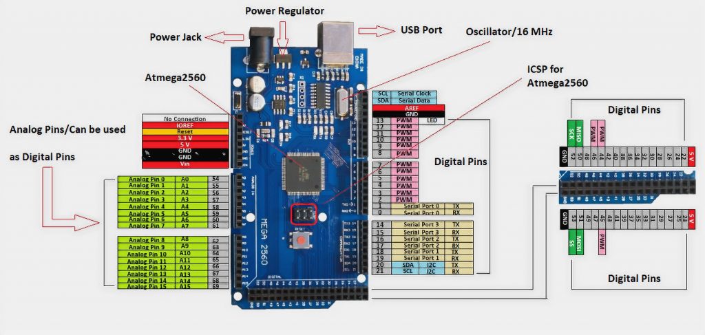
Arduino Mega 2560 Pinout
Power Pins
- VIN: Input pin for external power supply with a voltage range from 7 to 12 volts. Via the pin, you can consume voltage when the device is powered via the external power connector.
- 5V: Output pin from the voltage regulator on the board with an output of 5 volts and a maximum current of 800 mA. It is not recommended to power the device through the 5V pin – you risk burning the board.
- 3.3V: Output pin from voltage regulator with 3.3 volt output and maximum current 150 mA. It is not recommended to power the device through the 3V3 output – you risk burning the board.
- GND: Earth pins.
- IOREF: The contact provides the expansion boards with information about the operating voltage of the microcontroller. Depending on the voltage, the expansion board may switch to the appropriate power supply or use level converters.
- AREF: A pin to connect the external ADC reference voltage to which analog measurements are made using the analogReference() function with the “EXTERNAL” parameter.
I/O Ports
- Digital I/O: Pins 0-53
The logical unit level is 5 V, zero is 0 V. Maximum output current is 40 mA. Retaining resistors are connected to the contacts, which are switched off by default but may be enabled programmatically. - PWM: Pins 2-13 and 44-46
Allows outputting analog values as a PWM signal. The PWM bit rate does not change and is set to 8 bits. - ADC: Pins A0-A16
Allows presenting analog voltage in digital form. The ADC bit does not change and is set to 10 bits. The input voltage range is from 0 to 5 V. If more voltage is applied, you will kill the microcontroller. - TWI/I²C: Pins 20(SDA) and 21(SCL)
For communication with the periphery via the I²C interface. Use the Wire library for work. You can check Arduino LCD I2C tutorial here. - SPI: Pins 50(MISO), 51(MOSI), 52(SCK), and 53(SS).
To communicate with the periphery through the SPI interface. For work – use the SPI library. - UART: pins 0(RX) and 1(TX), 19(RX1) and 18(TX1), 17(RX2) and 16(TX2), 15(RX3) and 14(TX3).
It is used to communicate the Arduino board with a computer or other devices over a serial interface. Pins 0(RX) and 1(TX) are connected to the corresponding pins of the ATmega16U2 microcontroller, which acts as a USB-UART converter. To work with the serial interface – use the Serial library methods.
Circuit Diagram
Download the circuit diagram Arduino MEGA 2560 in PDF.
Arduino Mega Features
- Microcontroller: ATmega2560
- Core: 8-bit AVR
- Clock frequency: 16 MHz
- Flash memory capacity: 256 KB (8 KB takes the loader)
- SRAM memory capacity: 32 KB
- EEPROM memory capacity: 4 KB
- I/O ports total: 54
- Ports with ADC: 16
- ADC discharge: 10 bits
- PWM ports: 15
- PWM Bit: 8 bits
- SPI hardware interfaces: 1
- Hardware interfaces I²C / TWI: 1
- UART / Serial Hardware Interfaces: 4
- Rated operating voltage: 5 V
- Maximum pin output current 5V: 800 mA
- Maximum output current of Pin 3V3: 150 mA
- Maximum current from the pin or to pin: 40 mA
- Permissible input voltage from an external source: 7-12 V
- Dimensions: 4.61 x 2.36 x 0.98 inches
Conclusions
There are many in the network, both supporters and opponents of Arduino boards’ 8-bit architecture – they are trying to displace the debug boards STM family, and sometimes compared with single-board microcomputers.
However, Arduino’s age will continue for a long time, as it is a simple platform for fun mastering electronics and microcontrollers.
Learn microcontrollers and implement high technology in your everyday life.


