

Digital pins on the Arduino can take high or low values. This property is used to control most external motors, sensors, etc.
But sometimes, there are limitations due to the fact that the devices require higher currents than the Arduino can provide. Judging by the characteristics, the Arduino boards only provide us with 20mA.
If you work too often with currents that exceed these recommendations, you will not only have an unreliable electrical circuit, but you can also damage your Arduino controller.
Instead, you will need to connect the required amperage. One of the options is to use a relay. Sometimes you will also need transistors.
Working Principle of Relay
The working principle of the relay is as follows. Supply voltage to the electromagnetic coil. There is a field in the coil, which attracts a metal foot. In its turn, the foot mechanically closes the load contacts.
With the help of an Arduino and a relay, we control the process of switching on or off in the same way as we switch on or off the light in the house – by giving the command to short or open. The Arduino sends a signal, while the very closing or opening of the “powerful” circuit will relay special internal mechanisms. The relay can be imagined as a remote control, with which we perform the necessary actions using relatively “weak” signals.
The following parameters characterize the relay:
- Voltage or current of triggering.
- Release voltage or current.
- Triggering and releasing time.
- Operating current and voltage.
- Internal resistance.
Depending on the type of these internal disconnecting mechanisms and the device’s features, two main relay groups can be distinguished: electromechanical relays (switching by electromagnet) and solid-state relays (switching by special semiconductor components).
Electromagnetic and Solid-state Relays
Electromagnetic Relays
An electromagnetic relay is an electrical device that mechanically closes or opens a load circuit using a magnet. It consists of an electromagnet, a moving armature and a switch. An electromagnet is a wire that is wound on a ferromagnetic coil. The anchor is a plate made of magnetic material. Some models may have additional electronic components built-in: a resistor for more accurate relay operation, a capacitor to reduce interference, a diode to eliminate overvoltages.
The relay operates due to the electromagnetic force in the cores when the current is applied to the coil coils. The spring holds the armature at its original state. When the control signal is given, the magnet starts to attract the armature and close or open the circuit. When the voltage is cut, the armature returns to the initial position. Control voltage sources can be sensors (pressure, temperature, etc.), electrical circuits and other devices that supply low current or low voltage.
Electromagnetic relay is used in automation circuits when controlling various technological installations, electric drives and other devices. The relay is designed to regulate voltages and currents, be used as a storage or conversion device, and record deviations of typical values’ parameters.
Types of Electromagnetic Relays:
- The control current can be either direct or alternating. In the first case, the device can be neutral or polarized. For alternating current, the armature is made of electrotechnical steel to reduce losses.
- Reed relay. For the anchor, the process of closing and opening is carried out by moving the anchor, for the reed is characterized by the absence of a core, the magnetic field affects the electrode with contacts.
- Speed – up to 50 ms, up to 150 ms and from 1 s.
- Protective coating – sealed, shrouded and open.
Compared with semiconductor devices, the electromagnetic relay has advantages – it is inexpensive, switching high load with small device size and low heat release on the coil. Among the disadvantages can be distinguished by slow response, interference and complexity of switching inductive loads.
Solid-state Relays
Solid-state relays are considered an excellent alternative to electromagnetic. They are a modular semiconductor device, which is produced by hybrid technology. The relays have transistors, TRIACs or thyristors. Compared to electromagnetic devices, solid-state relays have several advantages:
- Long service life.
- Speed of operation.
- Small size.
- No extraneous noise, no acoustic interference, contact rattling.
- Low power consumption.
- High-quality insulation.
- Resistant to vibration and shock.
- No arc discharge, which allows working in hazardous areas.
Work on the following principle:
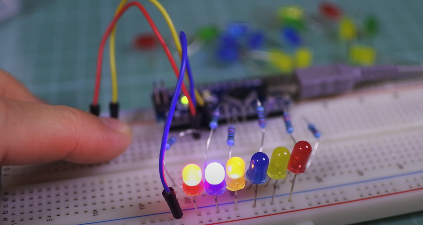
- The control signal is fed to the LED (here guide how to connect LED to Arduino).
- There is galvanic isolation of the control and switching circuits.
- The signal is transferred to the photodiode matrix.
The power key regulates the voltage.
Solid-state relays also have several disadvantages. First, when switching, the device is heated. An increase in the device’s temperature leads to limiting the adjustable current – at temperatures above 60 degrees, the current decreases, the maximum operating temperature of 176 degrees.
The following features classify solid-state relays:
- Load type – single-phase and three-phase.
- Control method – switching occurs at the expense of direct voltage, alternating or manual control.
- Switching method: control of transition over zero (used for low-inductive, capacitive and resistive loads), accidental switching (inductive and resistive loads that require instantaneous operation) and phase control (change of output voltage, power regulation, incandescent lamp control).
Relays in Arduino Projects
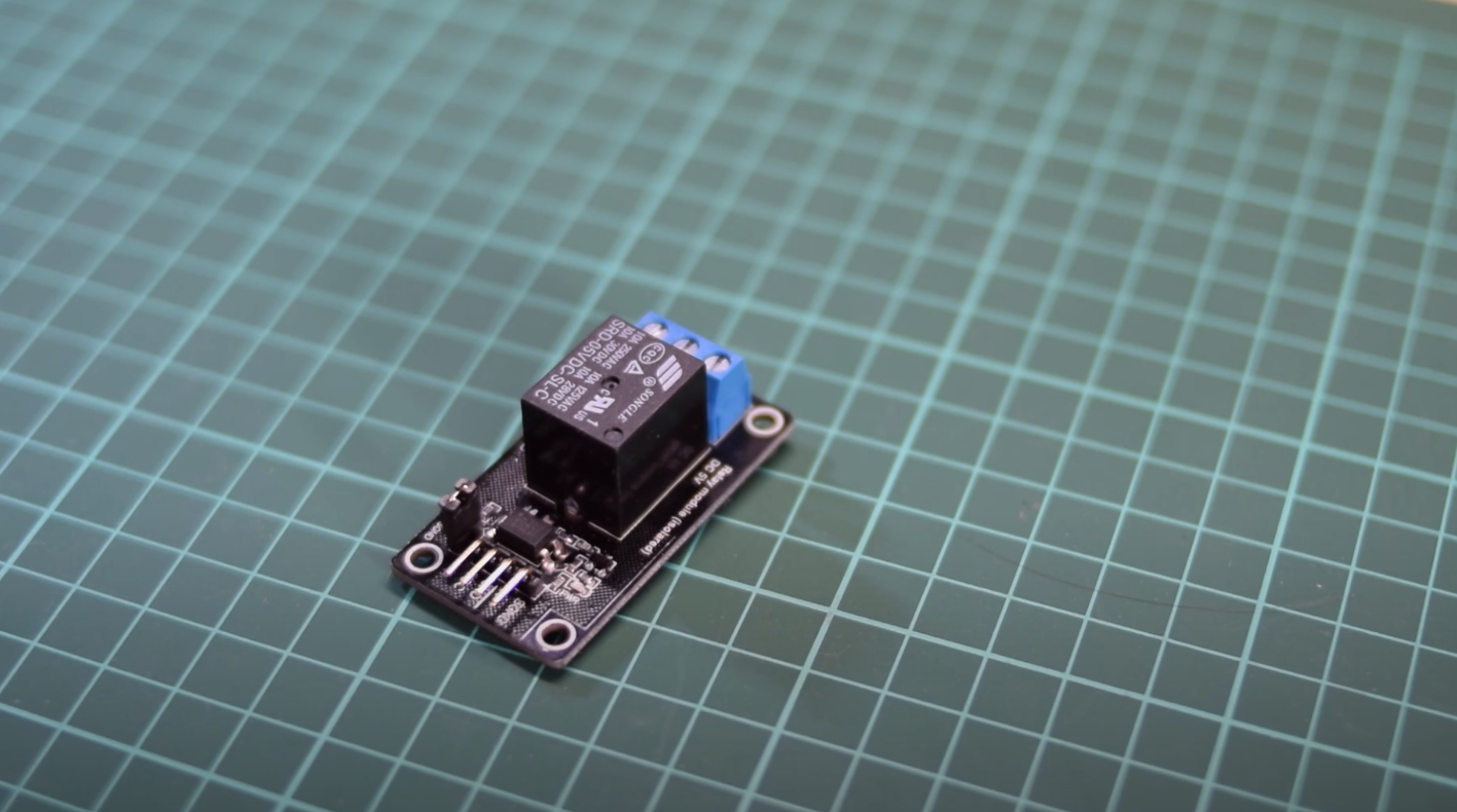
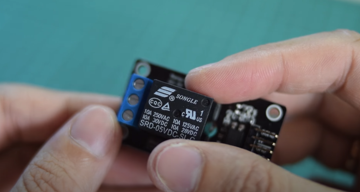
The Arduino board’s most common relay is executed as a module, for example, SONGLE SRD-05VDC. The device is controlled by a 5V voltage and can switch up to 10A 30V DC and 10A 250V AC.
The circuit diagram is shown in the picture. The relay consists of two unrelated circuits – control circuits A1 and A2 and controlled circuit 1, 2 and 3.
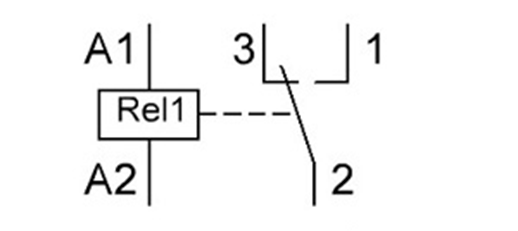
There is a metal core between A1 and A2. An anchor (2) will be attracted to it if an electric current is applied to it. 1, 3 – fixed contacts. If there is no current, the armature will be near contact 3.
Connecting the Relay to the Arduino
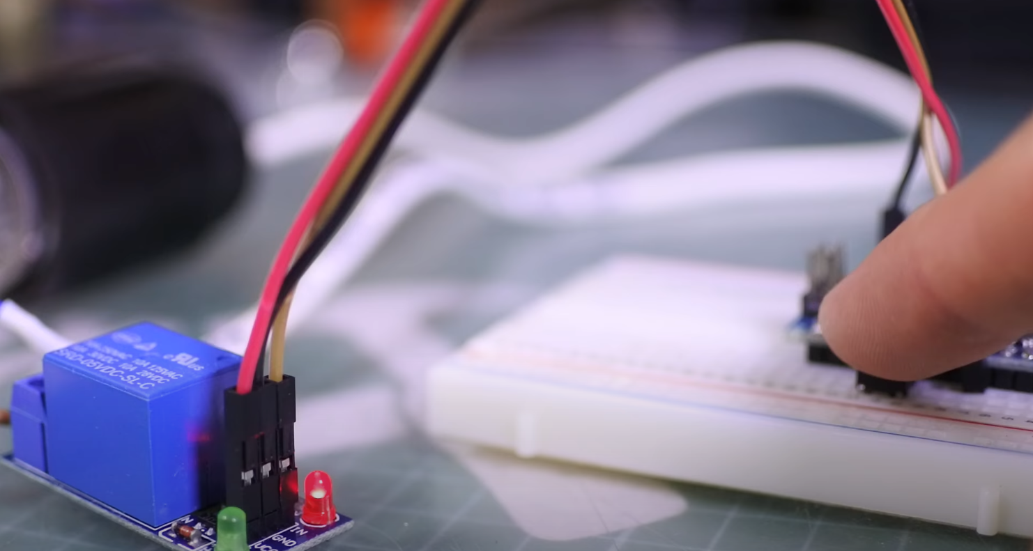
Let us consider a single-channel relay module. It has only 3 contacts. They are connected to Arduino Uno as follows: GND – GND, VCC – +5V, In – 3. Input relay – is inverted so that the high level on In turns off the coil, and low – turns on.
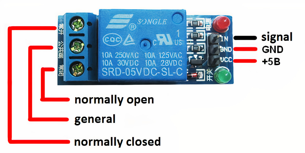
LEDs are needed for an indication – when the red LED1 lights up, voltage is applied to the relay. When the green LED2 lights up, a short circuit occurs. When the microcontroller is switched on, the transistor is closed. The transistor shall need a minus and shall be supplied with the function digitalWrite(pin, LOW) to open it. The transistor shall open, current shall flow through the circuit, and the relay shall trip. The transistor has to be opened, the current shall flow through the circuit, and the relay shall be triggered. The digitalWrite(pin, HIGH) shall be applied to the base to switch it off.
Arduino Relay Control: Sketch
The examples were tested on Arduino Uno, but they can be easily applied to other Arduino boards: Uno, Mega, Nano.
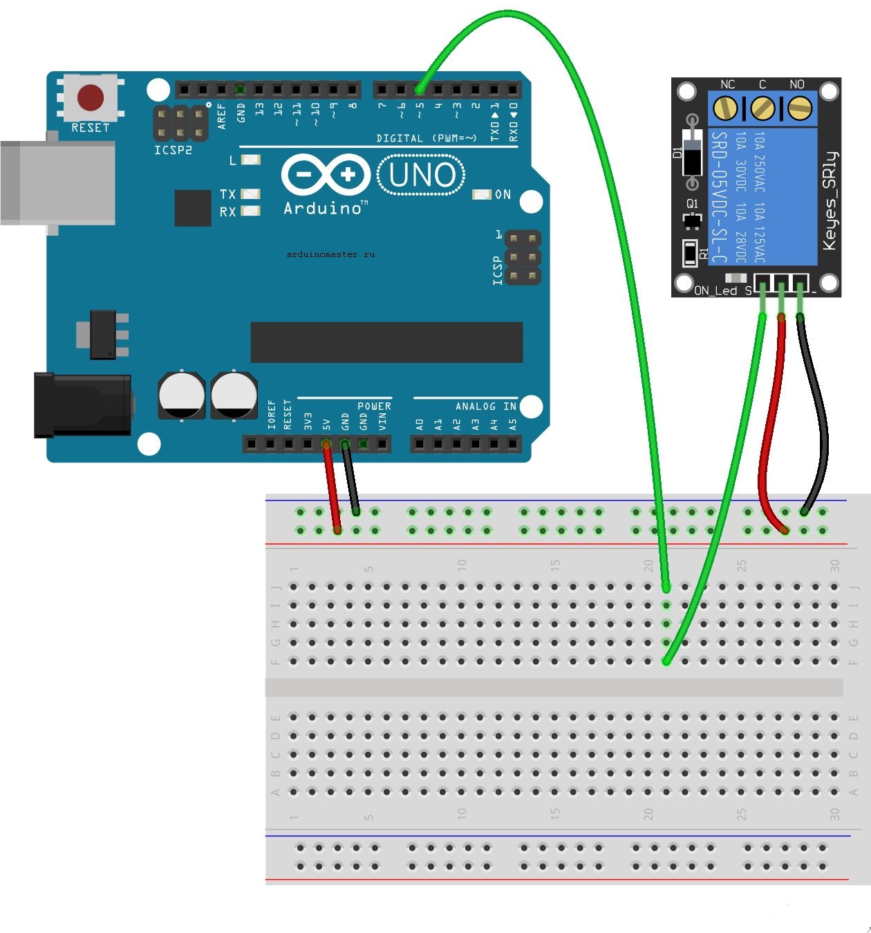
Connection Diagram
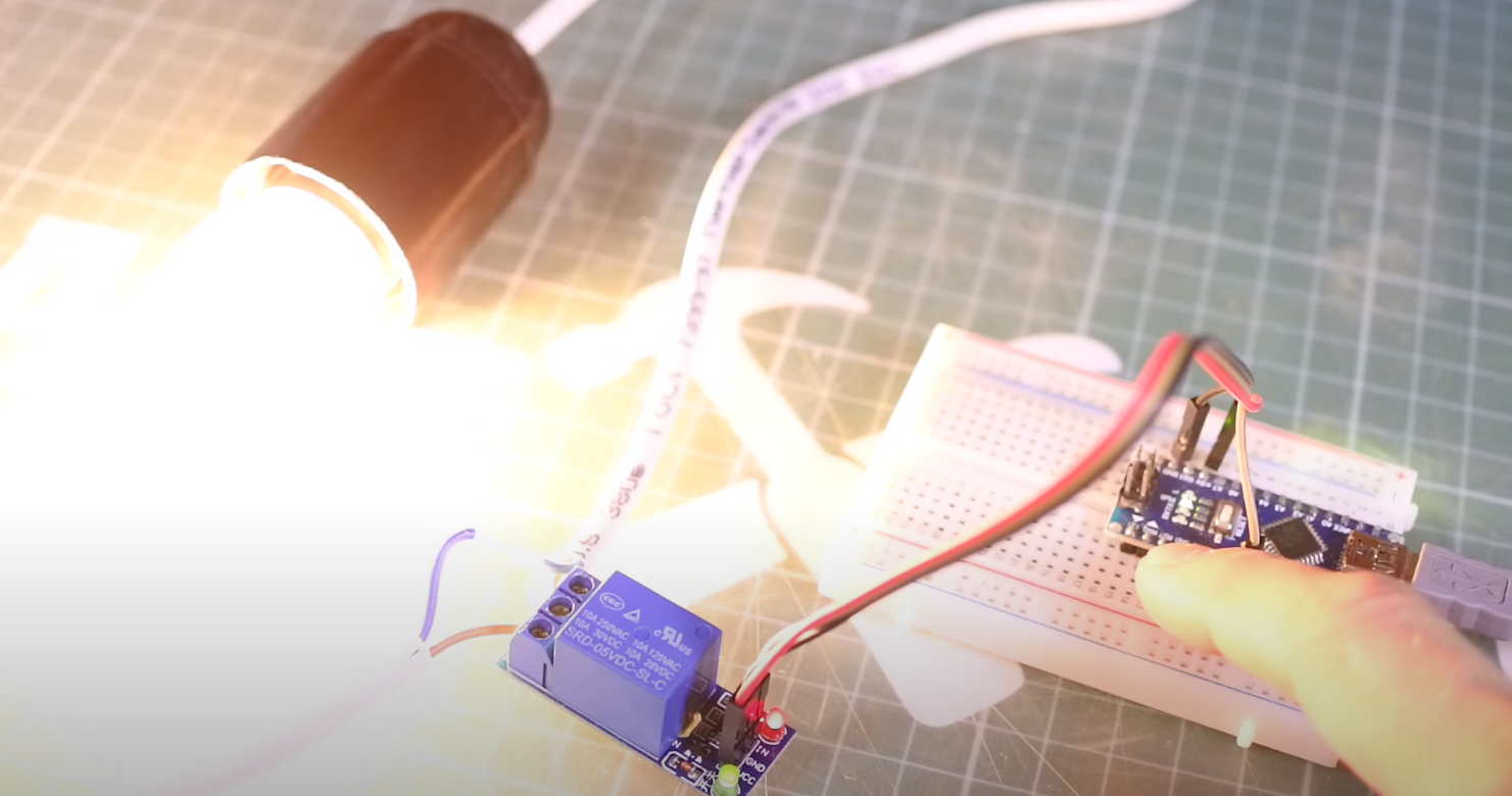
In this example, the standard Arduino relay module is used, on which all necessary elements for connection to. The wiring diagram is very simple: the relay module is connected to the 5 pins of the Arduino board. At the same time, for simplicity, we may not even connect the real load – the relay will click at each state change, we will hear these clicks, and we will understand that the sketch works.
Sketch for Working with Relays
/*
 * A sketch for Arduino relay control
 * We use SONGLE SRD-05VDC relay
 * The relay is OPEN when a low signal level (LOW) is applied to the control pin.
 * Relay CLOSES when a high-level signal (HIGH) is applied to the control pin.
 *
 * In this example, we simply open and close the relay every 5 seconds.
 *
 * PIN_RELAY contains the pin number to which the relay we will control is connected
 *
 * In the setup function, set the initial position of the relay (closed).
 * If a load (e.g., a light bulb) is connected to the relay, it will be on and off every 5 seconds after the sketch is started.
 *
 * To change the blinking period, you need to change the delay() function parameter: set 1000 milliseconds and get 1 second of delay.
 *
 * In real projects, the relay is switched on in response to the detection of any external events through the connection of sensors.
 *
 */

#define PIN_RELAY 5 // Define the pin used to connect the relay

// In this function we define the initial settings
void setup()
{
  pinMode(PIN_RELAY, OUTPUT); // Declare pin relay as output
  digitalWrite(PIN_RELAY, HIGH); // Switch off relay - send high signal
}
void loop()
{
  digitalWrite(PIN_RELAY, LOW); // Switch on the relay - send low signal level
  delay(5000);
  digitalWrite(PIN_RELAY, HIGH); // Switch off relay - send high signal level
  delay(5000);
}
Relay Control Sketch with Motion Sensor
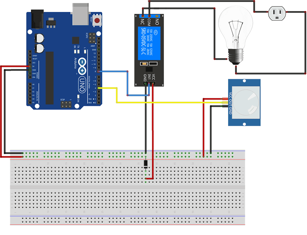
In real projects, the relay state change should take place in response to some medium reaction. For example, it is possible to switch on the light in response to the triggered motion sensor signal by closing the circuit with the relay. In this sketch, we will consider such a connection option.
Relay Connection Diagram
It should be understood that in real projects, they do without Arduino at all – just connecting the sensor signal output to the relay.
Example of a Sketch
In this example, we will add to the loop check of the PIR sensor using the function digitalRead(). If we get HIGH, it means that the sensor is triggered, and we perform the action – switch on the relay. If we connect a light bulb to it, it will light up. But, like in the previous example, you can just listen to the clicks.
/*
   Sketch for Arduino relay control with PIR sensor

   PIN_RELAY contains the pin number to which the relay we will control is connected.
   PIN_PIR contains pin number with connected PIR sensor

   In the setup function, we set the initial position of the relay (closed).
   In the body of the loop function, we check the presence of a high level of the signal from the sensor using the digitalRead function.

   For debugging, the current sensor value is displayed in the port monitor window.
*/


#define PIN_RELAY 8 // Define the pin used to connect the relay
#define PIN_PIR 5 // Define the pin used to connect the PIR sensor

// In this function, we define the initial settings
void setup()
{
  Serial.begin(9600);
  pinMode(PIN_RELAY, OUTPUT); // Declare pin relay as output
  digitalWrite(PIN_RELAY, HIGH); // Switch off relay - send high signal
}
void loop()
{

  int val = digitalRead(PIN_PIR); // Read the value from the motion sensor into a separate variable

  if (val == HIGH) {
    Serial.println ("Sensor triggered");
    digitalWrite(PIN_RELAY, LOW); // Switch on the relay - send low level signal
  } else {
    digitalWrite(PIN_RELAY, HIGH); // Switch off relay - send high signal level
  }

  delay(1000); // Check the values once per second.
}
Disconnect your USB cable from your personal computer and connect an external power supply to the Arduino and relay. Give your Microcontroller time to reboot. If everything has been done correctly, you should hear the characteristic click of a relay that will close and open the contact every two seconds.
Arduino Relay Module Specifications
Here, we present a table with key specifications of Arduino Relay modules to provide an overview of their characteristics.
| Specification | Description |
|---|---|
| Number of Channels | The number of independent relay channels available on the module. |
| Input Voltage (V) | The voltage level required to activate the relay, usually provided by the Arduino board. |
| Maximum Current (A) | The maximum current that the relay contacts can handle without damage. |
| Maximum Voltage (V) | The highest voltage level that the relay can safely switch. |
| Opto-Isolated | Indicates whether the relay module has opto-isolation for improved electrical isolation and safety. |
Explanation:
- Number of Channels: This specification represents the number of independent relay channels present on the module. Each channel can control a separate high-power device.
- Input Voltage (V): The relay module requires an input voltage to activate the relay coil, typically provided by the Arduino board. This voltage is crucial to trigger the relay and control the connected load.
- Maximum Current (A): This value indicates the maximum current that the relay contacts can handle without getting damaged. It is important to ensure that the relay can handle the current requirements of the load.
- Maximum Voltage (V): The maximum voltage specifies the highest voltage level that the relay can safely switch. Exceeding this voltage may lead to relay failure or potential hazards.
- Opto-Isolated: If a relay module is opto-isolated, it means it has built-in optical isolation to protect the Arduino board from voltage spikes and surges that may occur on the load side.
When selecting an Arduino Relay module, consider these specifications based on your project requirements. Each parameter plays a vital role in determining the compatibility, safety, and overall performance of the relay module with your high-power devices.
Final Words
This tutorial has provided a comprehensive understanding of how relays work and how they can be interfaced with an Arduino board. With the help of this tutorial, beginners can now easily automate their projects with the use of relays. It is important to note that relays should be used with caution and safety measures must be taken to avoid any electrical hazards. With practice and experimentation, beginners can master the use of relays and create more complex projects with ease.
Leave your comments, questions and share your personal experience below. New ideas and projects are often born in the discussion!


Which resistor converts the voltage to 3 volts?
Hello, Tom! A resistor usually does not convert voltage, it “consumes” it.
If you mean consumption, it depends on several parameters. Go to any website to calculate the resistance of the resistor, there substituting the parameters, you can easily get the result.