

In this tutorial, we will learn how to connect an LED to an Arduino board properly and how to organize its control with a sketch. You will need an Arduino Uno, Nano or Mega board, and the Arduino IDE program installed on your computer to work with projects. If you can’t assemble the sketch with your own hands, you can use the controller board’s built-in LEDs.
Connecting the LED to the Arduino
LED is one of the most common electronic components used in electrical projects. And it is natural that any DIY project starts with examples of work with light – flashing, flickering, switching. There are many LEDs of different versions and models in different housings and with different characteristics. We will use the most straightforward and cheapest components, which can be easily purchased in any online store.
Connection Rules
We need to know about LEDs (except that they glow) because they are semiconductor devices. Light in the form of emitted photons appears in a special layer (p–n junction) when a certain current passes through it. The principle of operation of the LED is shown in the following picture.
When connecting the LEDs, it is important to know the two main rules:
- The LED has positive and negative contacts, so it is important to observe the polarity when connecting.
- The LEDs have limits on the current flowing through them, so it is important to ensure the correct power supply mode. However, this applies to all electronic devices.
Polarity of LEDs
The first rule is easy to follow if you know where the LED is minus and where the plus is. Here the marking rules come to the aid. We look at the legs and see that they are of different sizes. A longer leg means a plus. Suppose there is no possibility to compare the length, or someone has already cut off a part of the legs before you. In that case, we feel the body (it will be difficult to determine visually) – on one side, the body is slightly trimmed (beveled), on this side, there is a minus.
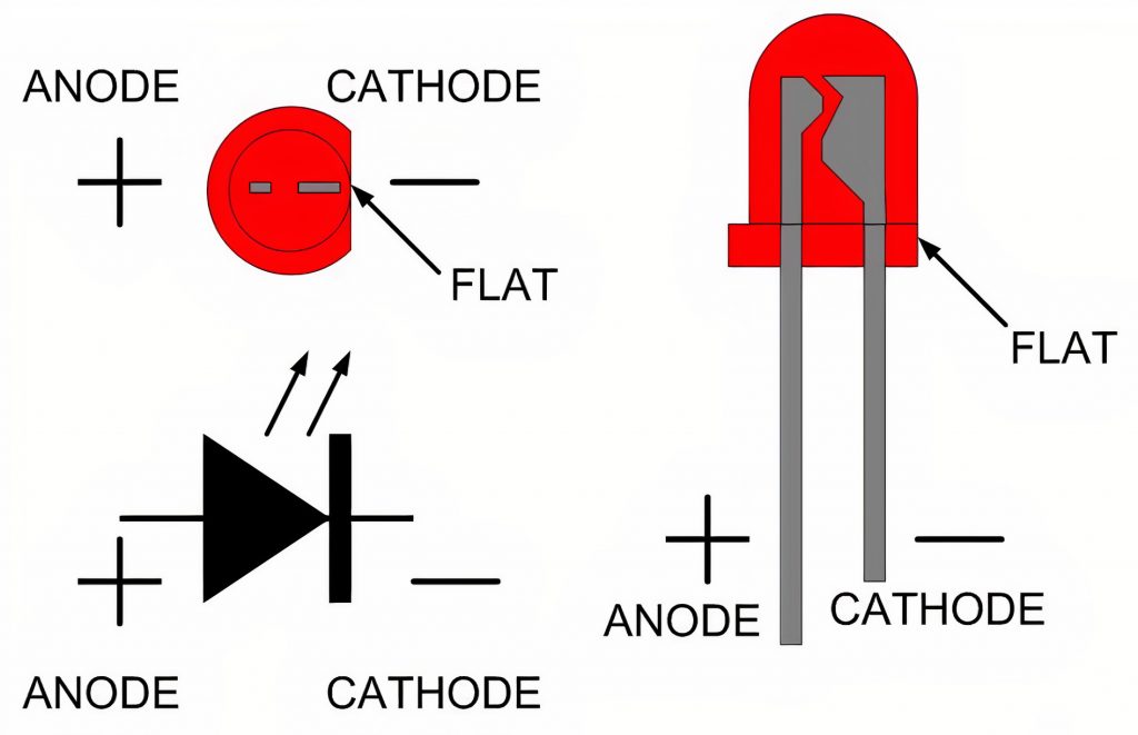
What happens if you mix up the legs and change the polarity of the connection? Luckily – nothing. Nothing will burn, but nothing will glow either. The diode, which is switched on incorrectly, opens the circuit. Of course, up to a certain limit, because if we supply enough current, sooner or later, there will be a breakdown, and the device will stop working at all.
Current Limit
The current limiting rule is also easy to implement. All you need to do is get the maximum current for a given model from your LED’s specification and add resistance to the circuit to provide the desired current in the circuit. All this can be easily calculated using Ohm’s law and the numerous calculators available on the Internet. In order not to complicate the process with unnecessary calculations (we did this in another article), we give the final result for the Arduino.
In our first projects for the most common LEDs available in the starter kits, we will use resistors 220 Ohms. If you add a bigger denomination resistor to the circuit, nothing terrible will happen – just a diode will not shine so brightly.
LED Connection Diagram
Connecting the LED to the electrical circuit is a simple enough operation. It is necessary to connect the corresponding legs with pros and cons. Connect the long leg to the part of the circuit that leads to a plus. It is important not to forget to connect a resistor to the circuit.
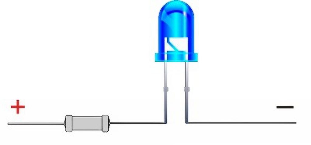
The question may arise about how to connect the wires. We can hold them with our hands and teeth. We can do a twist; we can sleep them. But the easiest and most reliable way to connect is to use a breadboard.
Connecting Scheme to the Board Arduino Nano or Uno
To connect an LED to the Arduino, you need to understand where on this board will be the plus, where the minus. After all, an LED is an electrical device. For its work, you need an electrical circuit with a plus and minus. The first thing you can do is to connect the power to the 5V pin of the Uno board. The light will be on, but it is impossible to control such a device with a sketch. The light will stay on as long as the power is on. Of course, you can turn off the power and take the board to sleep in the program, but this is the subject of a separate article.
The correct connection option is to use the board pins (connectors), on which we can supply voltage from the sketch. There is nothing complicated here if you imagine the Arduino board as a battery with many positive and negative poles. We turn on or off the desired connectors, applying voltage and current to the devices connected to them.
We will start with the negative poles. All board disadvantages are denoted by one word – GND, shortened from the ground – earth (“ground” or “housing” is often called a common line for an electrical circuit). On the board Arduino Uno or Nano, you can find three such contacts: near 13 pin and on the other side, in the area of power connectors.
All other digital or analog pins (with numbers or designations A0-A5) can be both pros and cons. If we indicate in the program that we need to apply a voltage (high signal level) to the desired port, it becomes a plus. If we specify a low signal level, the pin becomes a “minus”. We will not go into the details and calculations; our task is to understand the basics.
Step-by-step Instruction
So, we need to connect an LED to the board. To do this, we connect the long foot to the plus, i.e., the part of the circuit that leads to the digital or analog connector of the board. But we do it not at once but through a resistor, which is then connected to pin 13. We connect the short leg (minus) to the minus – to the GND pin. This is how it looks on the diagram.
You can swap the resistor and the LED to connect GND to the resistor and then connect it directly to the digital pins. Nothing will change from that. If you want to swap the wires, be sure to note that the diode legs should have a long side to the wires that lead to the board pins and a short side to the GND pins.
To simplify your work, connect an LED to 13 pin, as shown in the diagram. Having assembled the circuit and turned on the power, we can see how our LED blinks already at the start. If the same initial sketch of a beacon is loaded in the board, after the initialization, the LED will blink, and you will see that now it blinks at a rate of 1 time per second.
Built-in LED in Arduino Uno and Nano
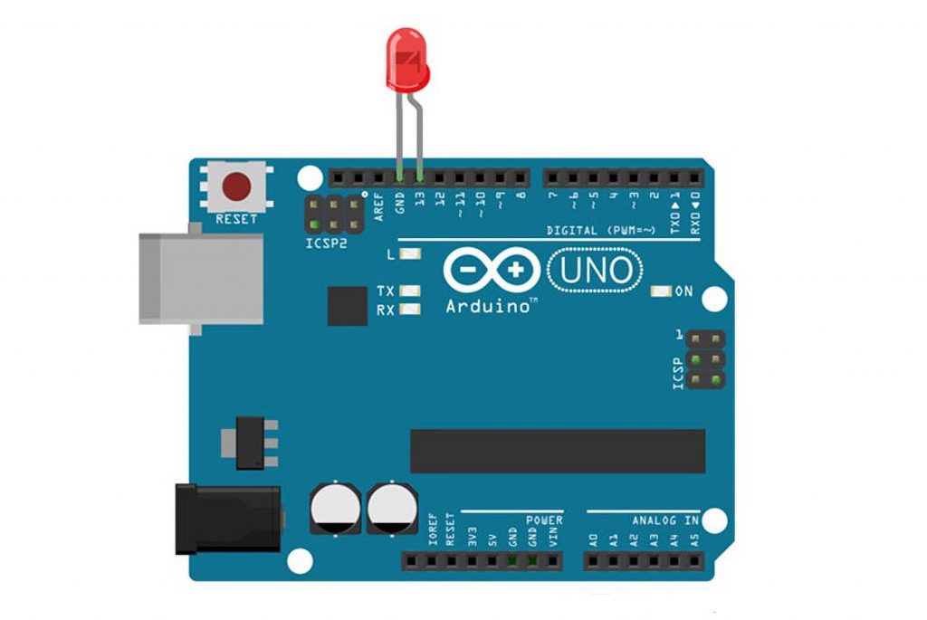
In fact, we do not need to know about the nuances of working with LEDs to begin practical activities. The first experiments can well be done with the built-in LED of the Arduino board. In the vast majority of boards, it will be connected to pin 13. You can easily find the board’s luminous elements – they light up and blink in different colors when switched on. These are the built-in LEDs.
Not all “light bulbs on the board” are available for us to control from the sketch. Some of them serve as indicators of data exchange through certain protocols (e.g., UART). Others inform us about power-up and operation of the board. An LED attached to the board’s pin 13 can light up and go off when the board is turned on, and then its operation is determined by the built-in sketch.
The number of light sources is limited on some board options, and 13 pins are not connected. This is done for energy saving because the light bulb always leads to increased electricity consumption. In some projects that require long battery life, “voracious light bulbs” have to be forced out.
Connecting Multiple LEDs
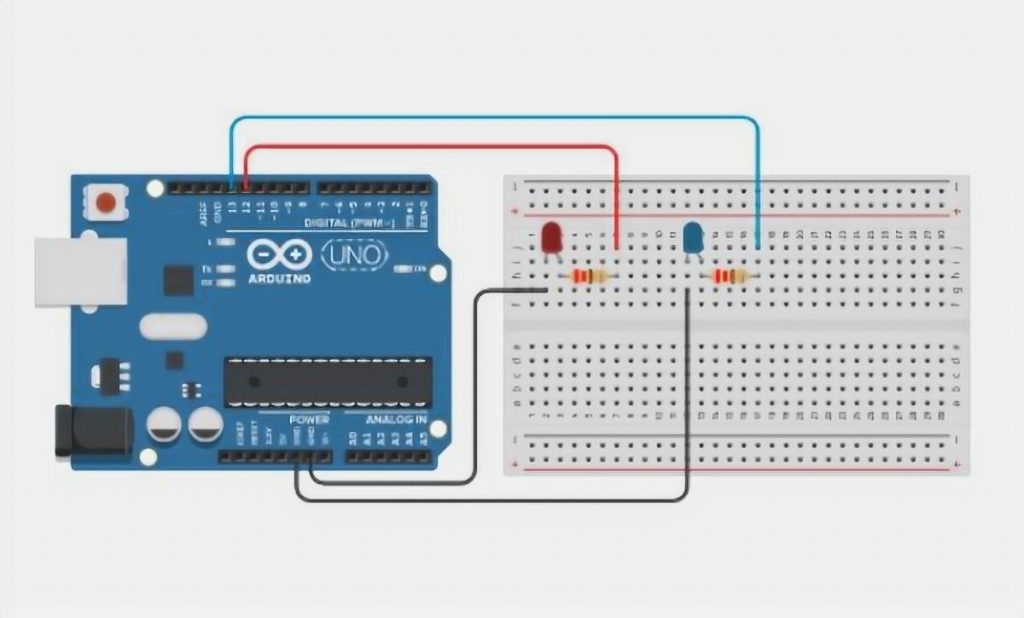
To connect several LEDs to the Arduino, connect them to its digital port on the same circuitry. For example, you can take two red and blue LEDs to create the Blink project by connecting their positive (long legs) pins to 13 and 12 pins, respectively, through resistance. The short legs are connected to the minus – grounding.
We already know that there are three connectors with this designation (“GND”) waiting for us on the board. You can connect to anyone. If there aren’t enough power connectors, we have three options.
To form the right power levels on the free pins. For example, by giving a low signal level at pin 5 in the sketch, we will get the necessary “minus” on this connector.
Use a breadboard that has excellent options for distributing “pros and cons” through common power lines (see the article on our website).
Use special Sensor Shield expansion boards that have power and ground pins separately for each pin.
In the same way, you can connect the following LEDs by starting a traffic light or LED strip project.
Keep in mind that connecting more than 3 LEDs puts quite a heavy load on the Arduino board power supply module. Therefore it is not recommended to switch on multiple LEDs for a long time at the same time.
LED Control
By connecting the LED to the Arduino, we get a very handy tool to control it. After all, we do not need to turn anything on or off physically. It’s enough to specify the program’s necessary instructions so that the board itself supplies voltage to the necessary pins, turning on or off our LED. Once we have loaded the program into the controller memory, we will force it to execute the algorithm we need every time the power is connected.
Switching the LED On and Off in Arduino
The LED will turn on when we give the pin to connect a high signal level (voltage). The digitalWrite function with the second parameter HIGH is responsible for this in Arduino. For example, for an LED connected to pin 12, the command will look like this: digitalWrite(12, HIGH);
We use the same command to turn off the LED but with the parameter LOW: digitalWrite(12, LOW). If we call the first command and then after a while the second command, the LED will first light up and then turn off. If we loop on and off, we will get a constantly turning on and off blinking beacon.
There are situations when the LED is not very bright, and it is not clear what has gone wrong here. In fact, you should check if you have forgotten to configure the pin as an output. This is done by adding the pinMode function (usually in the setup() block). For our version, the function will look like this: pinMode(12, OUTPUT);
The sketch below turns the LED on and off once per second. The delay() function is used to count down the time, which pauses the program execution for a specified number of milliseconds.
// the initialization function is started at program start

void setup() {
  pinMode(8, OUTPUT); // initialization of output 8 as "Output"
}

// the cycle function is started again and again after its execution.

void loop() {
  digitalWrite(8, HIGH); // LED on the output 8
  delay(500); // pause in program execution by half a second
  digitalWrite(8, LOW); // LED off on output 8
  delay(500); // pause in program execution by half a second
}
LED Brightness Control
We can not only turn the light on or off but also control its brightness. For this purpose, we use a special technology with the beautiful name PWM. By connecting to the controller’s PWM-enabled pins, you can adjust the luminous intensity using the analogWrite() function. We have to give it the pin number and the value from 0 to 255 as parameters. The bigger the number, the brighter the bulb will shine. For example, for pin 3, the example will look like this: analogWrite(3, 255) or analogWrite(3, 100). In the first case, the brightness will be maximally possible. In the second case, it will be much less.
You have to remember that not all pins of the controller support PWM. With Arduino Uno, Nano, based on ATMEGA328, the shims support pins 3, 5, 6, 9, 10, 11. The Mega board has many more such pins.
Comparison Table: Different Methods to Connect LED to Arduino
In this comparative study, we will explore various indicators related to connecting LEDs to an Arduino and compare different methods for doing so.
| Indicator | Method 1: Basic | Method 2: Using a Resistor | Method 3: PWM |
|---|---|---|---|
| Complexity | Low | Low | Medium |
| Required Components | Arduino Board, LED | Arduino Board, LED, Resistor | Arduino Board, LED, Resistor |
| Protection for LED | No | Yes | Yes |
| Brightness Control | No | No | Yes |
| Power Efficiency | Low | Medium | High |
| Best Suitable for | Simple ON/OFF scenarios | General LED projects | LED projects with varying brightness |
Explanation:
- Complexity: Method 1 is the basic method and has the lowest complexity, suitable for simple ON/OFF scenarios. Method 2 and Method 3 have slightly higher complexity but offer added features.
- Required Components: Method 1 requires only an Arduino board and an LED, making it the simplest setup. Method 2 and Method 3 require an additional resistor to protect the LED and the Arduino board.
- Protection for LED: Method 1 does not include any protective element for the LED. Method 2 and Method 3 both use a resistor to prevent excessive current flow and protect the LED from burning out.
- Brightness Control: Method 1 does not offer brightness control for the LED. Method 3 utilizes Pulse Width Modulation (PWM) to control the LED’s brightness.
- Power Efficiency: Method 1 is the least power-efficient since the LED is either fully ON or OFF. Method 2 improves efficiency by using a resistor, but Method 3 (PWM) provides the highest power efficiency as it adjusts the LED brightness dynamically.
- Best Suitable for: Method 1 is best for simple projects requiring basic LED control. Method 2 is suitable for general LED projects where protection is essential. Method 3 is ideal for projects demanding varying brightness levels, such as mood lighting or visual effects.
Remember, when working with electronic components, always ensure proper connections and follow safety guidelines to avoid damage to your components and board.
Conclusion
Connecting the LED to your Arduino circuit is not a difficult task. Just connect the legs in the correct order, and do not forget about the current limiting resistor. The main advantage of the Arduino in such circuits is the possibility of software control of the LED. We simply write the required algorithm in the program, load it into the controller, and the board turns on and off the pins we need.
You can connect several LEDs, but make sure that you don’t exceed the current limit as a result. You can not only turn the light on or off, but also control its brightness. To do this, we use pins that support PWM and analogWrite. Happy experimenting with LEDs and Arduino!


I’ve never worked with an Arduino before, but I decided to give it a try. I was surprised at how easy it was to get started. The LED was the first thing I wanted to try.
I followed a tutorial online and had the LED blinking in no time. It’s really satisfying to see something you built yourself working correctly. Now I want to try more things with the Arduino.