The weight sensor is a very important element in many Arduino projects. By changing the weight, you can recognize the mass and track and record changes to the object and then perform some actions. In this article, we will learn how to connect a weight sensor to an Arduino using load cells of various denominations and the HX711 chip as an analog-to-digital converter.
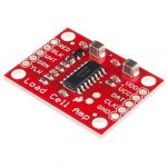 SparkFun Load Cell Amplifier is a small breakout board for the HX711 IC that allows you to read load cells to measure weight easily.
Load Cell Working Principle
The weight sensor’s work is based on changing any physical parameter proportional to the weight of the object being measured. The parameter depends on which element is used in the sensor. So when the load on the piezo-ceramic plate changes, the voltage removed from the electrodes at the ends of the piezo-sensor changes. When the capacitive sensor is used, the capacitance of the variable capacitor changes. This design uses a weight sensor made on an elastic resistor, and when the weight changes, its resistance changes, and therefore the voltage removed from the bridge circuit.
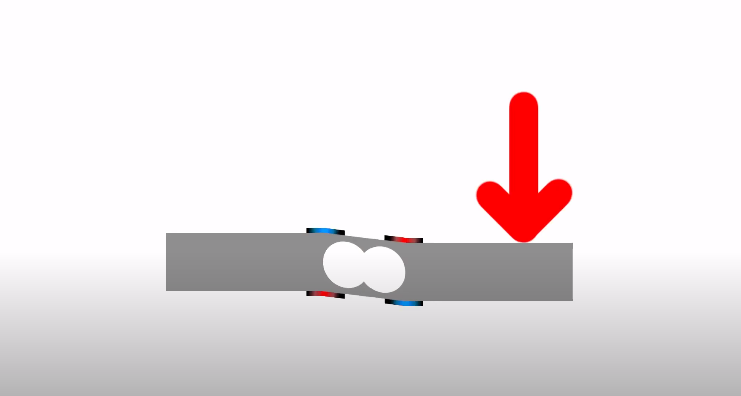
The sensor is a rectangular bar made of aluminum alloy, with a hole in the center. On its side surfaces are applied thin-film resistors connected by a bridge circuit, so the resistive sensor has 4 flexible outputs. All sensor elements are filled with an epoxy compound. Threaded holes are provided on the bar to fix it to the base and mount the plate under the measured load. The end side of the sensor is marked to indicate the maximum weight of the measured cargo. In order for the resistors to change their resistance, the strain gauge sensor must be fixed at one end on the base and at the other end of the load must act so that the deformation of the bar and, accordingly, the film resistors. In order to convert the analog signal from the output of the tensor sensor into binary code, an analog-to-digital converter (ADC) HX711 is used.
Load Cell and HX711
Integral chip HX711 is an analog-to-digital converter with a sample rate of 24 bits and a built-in low noise operational amplifier. The multiplexer allows selecting one of the two available input channels. Channel A has a programmable gain selection that can be 64 or 128. Channel B operates at a preset gain of 32.
An integrated voltage stabilizer is included in the chip, eliminating the need for an external stabilizer. Any pulse signal from an external source can be fed to the synchronization input; however, the ADC allows operation from a built-in oscillator.
Main technical characteristics of НХ711:
- ADC discharge – 24 bits
- Input amplification A – 64 or 128
- Input amplification B – 32
- Frequency of measurement – 10 or 80 times per second
- Supply voltage – 2.6-5.5 V
- Current Consumption – less than 10 mA
- Input voltage – ± 40 mV
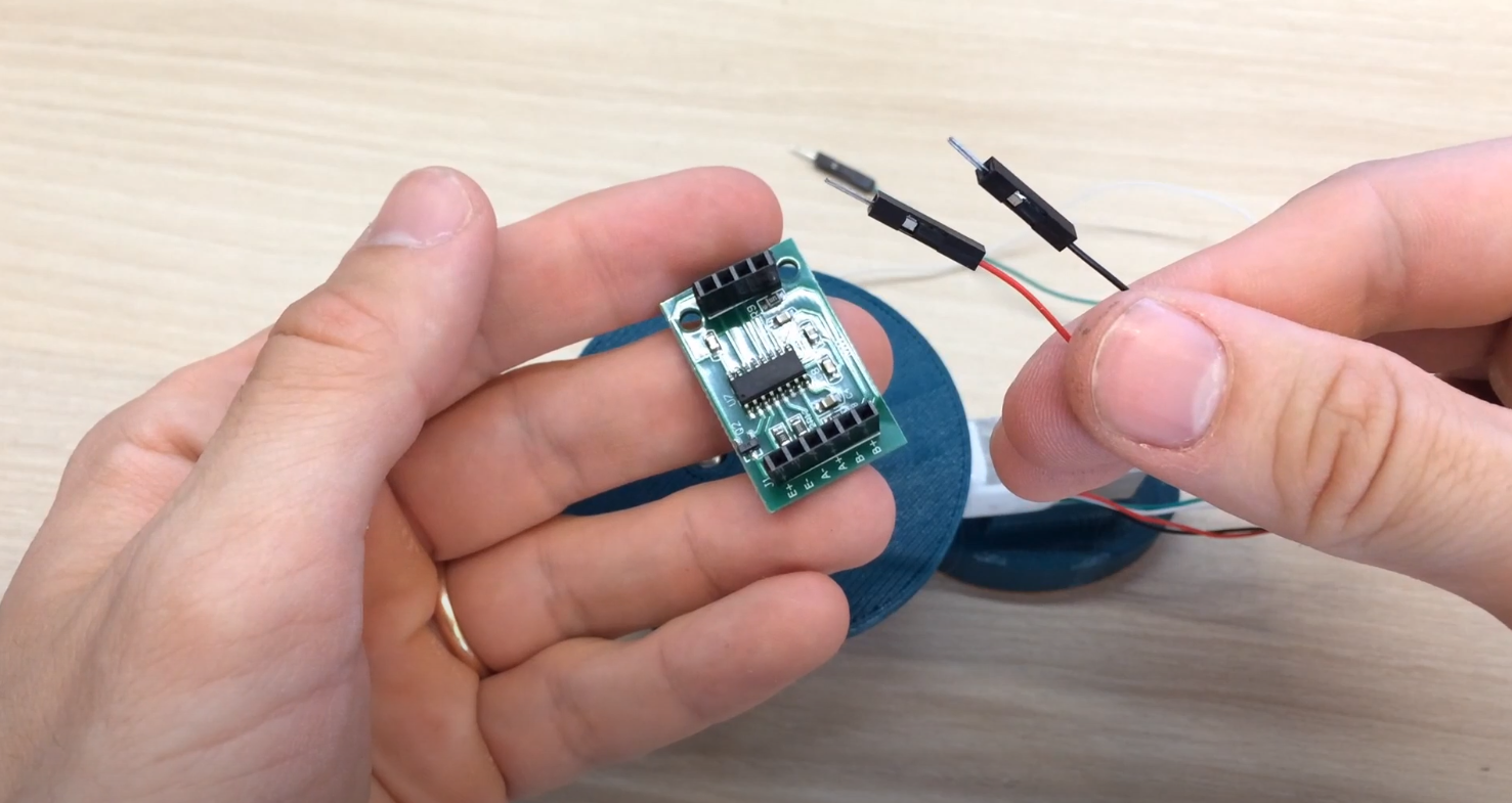
There are two connectors on the board with ADC – J1 and JP2, which have the following designations:
J1
- E -, E + tensor bridge power supply
- A -, A + differential input of channel A
- V -, V + differential input of channel V
JP2
- GND, VCC power supply
- DT, SCK – information buses
Connecting HX711 to Arduino
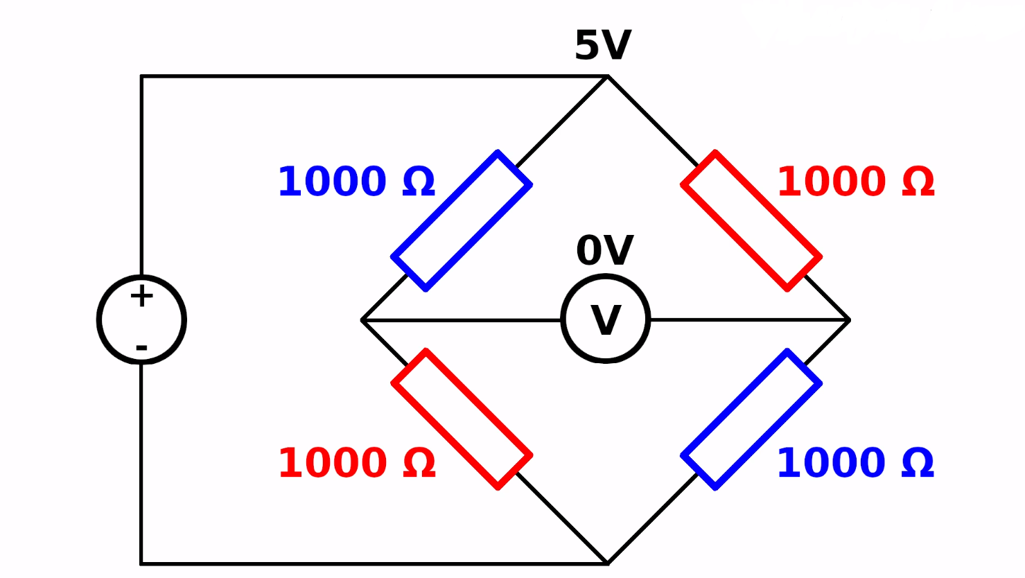
As the bridge circuit switches on the tensor resistors, 4 conductors with different color markings depart from the device. The reference voltage is fed to two arms of the bridge, and the output voltage is removed from the other two arms, which is fed to the input of the operating amplifier of the chip HX711. Connection by wire colors is performed as follows:
- Red – E +
- Black – E –
- White – A –
- Green – A +
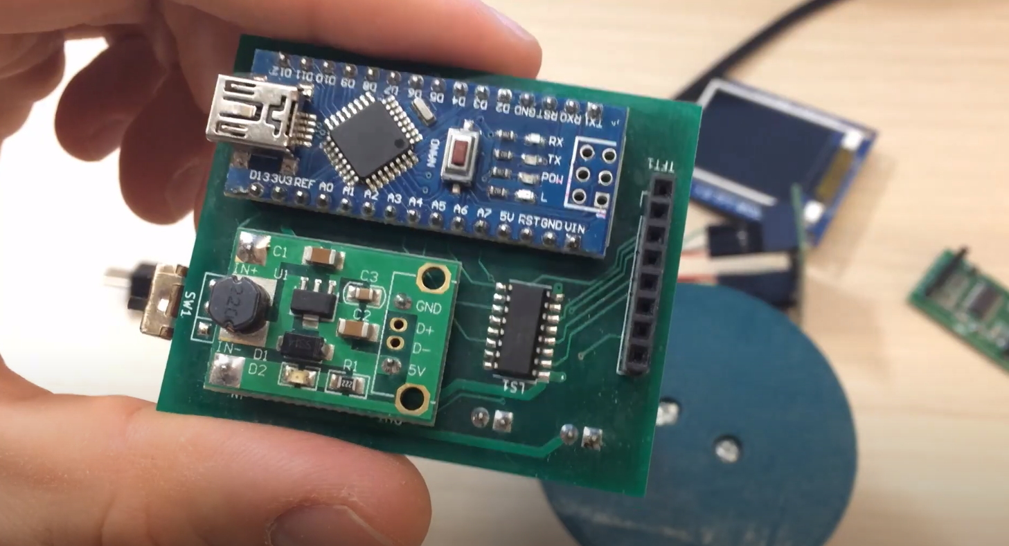
For further processing and transfer of information, the connection of HX711 to Arduino UNO is carried out. For this purpose, power contacts GND and VCC HX711 have connected to the points GND, and 5V POWER connector module Arduino UNO, and contacts DT and SCK are connected to points A1 and A0 connector ANALOG IN. Load sensor НХ711 through the controller Arduino UNO can be connected to the LCD 1602 or computer, using the USB port and standard libraries for Arduino.
HX711 Calibration Code
Since the voltage changes at the output of the measuring bridge, it is it that converts to binary code. The range of monitored voltages depends on the selected gain. If the ratio is 128, the range of measured voltages varies from – 20 mV to + 20 mV, the choice of the gain 64 determines the measurement limits from – 40 mV to + 40 mV and at a ratio of 32, the measurement limits are 80 mV and + 80 mV. These data will be correct only at +5 V supply voltage. If the input voltage exceeds the lower limit of the range, the ADC will give the code 800000h, and if the upper limit is 7FFFFh. The following codes can be used for calibration and measurement:
// code for calibration
#include "HX711.h"

HX711 scale(A1, A0); // DT, CLK

float Calibration_Factor_Of_Load_cell = -3.7; // this calibration factor is adjusted according to the load sensor
float U;
float O;

void setup() {
  Serial.begin(9600);
  Serial.println("HX711 calibration sketch");
  Serial.println("Remove all weight from scale");
  Serial.println("After readings begin, place known weight on scale");
  Serial.println("Press + or a to increase calibration factor");
  Serial.println("Press - or z to decrease calibration factor");

  scale.set_scale();
  scale.tare(); // Reset scale to 0
  long zero_factor = scale.read_average(); // Get basic reading
  Serial.print("Zero factor: "); // This can be used to eliminate the need to tare the scale. Useful in constant scale projects.
  Serial.println(zero_factor);
}

void loop() {

  scale.set_scale(Calibration_Factor_Of_Load_cell); // Adjust this calibration factor
  Serial.print("Reading: ");
  U = scale.get_units();
  if (U < 0)
  {
    U = 0.00;
  }
  O = U * 0.035274;
  Serial.print(O);
  Serial.print(" grams");
  Serial.print(" Calibration_Factor_Of_Load_cell: ");
  Serial.print(Calibration_Factor_Of_Load_cell);
  Serial.println();

  if (Serial.available())
  {
    char temp = Serial.read();
    if (temp == '+' || temp == 'a')
      Calibration_Factor_Of_Load_cell += 1;
    else if (temp == '-' || temp == 'z')
      Calibration_Factor_Of_Load_cell -= 1;
  }
}
Explanation of the code:
- A correction factor will be displayed on the port monitor, which should be used further when working with the scale sensor;
- If correction of the correction factor is necessary, a “+” or “-” should be sent to the Arduino board via the port monitor.
HX711 Load Cell Code
#include <HX711.h>
HX711 scale(2, 3); // ports DT, CLK

float calibration_factor = -3.7; // sensor calibration
float units;
float ounces;

void setup() {
   Serial.begin(9600);

   scale.set_scale();
   scale.tare(); // reset the sensor to 0
   scale.set_scale(calibration_factor); // apply calibration
}

void loop() {
   Serial.print("Reading: ");

   for(int i=0; i<10; i++) units =+ scale.get_units(), 10; // make measurements 10 times
   units / 10; // divide values by 10
   ounces = units * 0.035274; // convert values into grams

   Serial.print(ounces);
   Serial.print(" grams");
   Serial.println();
}
Explanation of the code:
- Using the correction factor from the first program, your scale should show a fairly accurate value in grams;
- You can download the Arduino hx711.h library with a description of the commands here.
Connecting HX711 Load Cell to Arduino: Indicator Comparison
This table presents a comparison of various indicators for connecting an HX711 Load Cell to an Arduino. The HX711 is a precision 24-bit analog-to-digital converter designed to interface directly with a bridge sensor, making it ideal for load cell applications. By evaluating these indicators, you can choose the most suitable configuration for your project.
| Indicator | Description |
|---|---|
| Complexity | The level of difficulty in setting up the HX711 Load Cell with Arduino. |
| Accuracy | The precision and reliability of measurements obtained from the load cell. |
| Cost | The financial expenses involved in connecting the HX711 Load Cell to Arduino. |
| Additional Components Required | The number of extra components needed to complete the connection. |
| Calibration | The ease of calibrating the load cell and Arduino setup for accurate measurements. |
Explanation of the Table:
- Complexity: This indicator assesses the level of difficulty in setting up the HX711 Load Cell with Arduino. A higher complexity may involve more intricate wiring or configuration steps, while lower complexity indicates a simpler and more straightforward setup process.
- Accuracy: The accuracy indicator reflects the precision and reliability of measurements obtained from the load cell. Higher accuracy means the readings closely match the actual values, while lower accuracy indicates potential variations or inaccuracies.
- Cost: The cost indicator represents the financial expenses involved in connecting the HX711 Load Cell to Arduino. Lower cost implies a more budget-friendly setup, while higher cost may involve additional expenses for specialized components or premium quality parts.
- Additional Components Required: This indicator denotes the number of extra components needed to complete the connection between the HX711 Load Cell and Arduino. Fewer additional components imply a simpler setup, while a higher number may suggest a more complex arrangement.
- Calibration: The calibration indicator measures the ease of calibrating the load cell and Arduino setup to ensure accurate measurements. Easier calibration means less effort is required to fine-tune the system, while a more challenging calibration process may demand more time and expertise.
Final Thoughts
Connecting a load cell to an Arduino board is a useful technique for measuring weight and other forces in various applications. This tutorial has provided a step-by-step guide on how to connect a specific load cell, HX711, to an Arduino board. Users can easily obtain accurate readings from the load cell by following the instructions carefully. It is important to note that load cells should be handled with care, and safety measures should be taken to avoid any damage or injury. With practice and experimentation, users can apply this knowledge to create more advanced projects that require load cell measurements.