
One of the priority issues for novice circuit designers is having the optimum number of outputs. Once all the training examples are mastered, the real-world tasks put this problem at the top of the agenda. For example, when connecting your first LED to the microcontroller, the circuit designer thinks about connecting 10-20 LEDs. The standard outputs of the Arduino Nano may not be enough.
Even if you have an Arduino Mega with 54 outputs at hand, real-world applications may require much more.
To implement the project in this article, we will need the following components:
- An Arduino Uno R3
- A set of LEDs and resistors
- A shift register 74HC595
- A 400 point breadboard
- A set of breadboard “daddy/paddy” wires
On the surface, there is a ready solution – to buy another microcontroller, but this is expensive and not pragmatic. Moreover, there is a serious problem of synchronizing two controllers in such a case, which is much more challenging to solve.
A more elegant way is to use the output shift register, an eight-bit 74HC595 chip, for example.
The bit depth of the chip used is the basic characteristic of the shift register. For example, the 74HC595 can connect up to eight devices with only three controller pins!
The economy of using this chip is visible to the naked eye, but if this is not enough, you can connect the shift registers in a cascade (i.e., one after the other, in a chain). In this case, the number of connected devices will increase by a multiple of eight with each chip, and the number of pins of the Arduino will remain equal to three.
The disadvantage of using 74HC595 chips is that it is impossible to implement PWM – pulse width modulation. The thing is that all chip outputs will have one of two logical values – 0 or 1.
As a result, when using dimmable LEDs, you should pay maximum attention to the drivers.
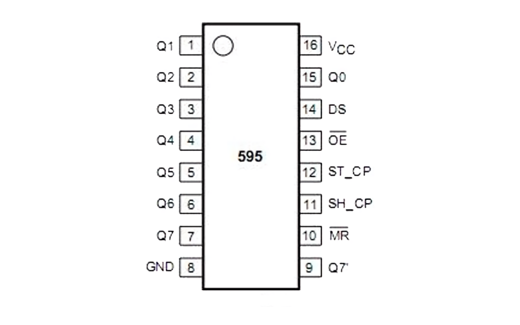
74HC595 Chip Design and Pinout
The pinout of the microchip is very simple due to the special marking in the form of a circle, from which the pin counting starts. In addition, all pins of the shift register have high resistance so that the operation of the chip is not affected by the possibility of changing the voltage at the outputs with other elements. This makes it efficient to control different registers with the same elements.
When one is active, the other is put into a high impedance state. In case only one register is used, the second one is grounded. Then, they are connected to the power rail for the normal operation of the Vcc register and the MR input.
The inputs DS, SH_CP, and ST_CP are used to control the shift register: when the position of SH_CP changes from LOW to HIGH, 1 bit is read from input DS. The reverse switch ensures that the reception of information is terminated.
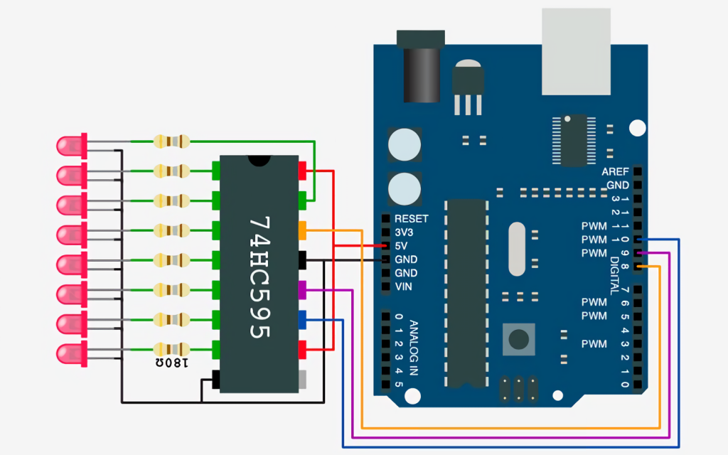
To simplify the use of the 74HC595 chip, you can use special libraries. For example, the schematic designer only needs to connect the shift register inputs to specific Arduino outputs.
The input of the 74HC595 is a high-frequency supply of pulses. For this reason, the filtering has to be done with a capacitor with a capacity of 0.1µF. Therefore, the interference is minimized at the input of ST_CP, and 220 Ohm resistors and LEDs are used as load.
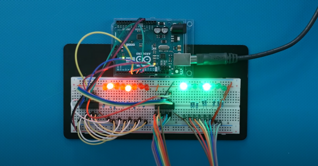
How to Сontrol the LEDs?
Before we start the practice it is necessary to check the connection of all elements and to load the following sketch into the microcontroller:
//Contact SH_CP
int SH_CP = 10;
//Contact ST_CP
int ST_CP = 9;
//Contact DS
int DS = 8;

void setup() {
   // let's set the outputs SH_CP, ST_CP, DS
   pinMode(SH_CP, OUTPUT);
   pinMode(ST_CP, OUTPUT);
   pinMode(DS, OUTPUT);
}

void loop() {
   for (int i = 0; i < 256; i++) {
      // Call the start of data reception
      digitalWrite(ST_CP, LOW);
      // Sequential data transfer to DS pin
      shiftOut(DS, SH_CP, MSBFIRST, i);
      // Call the end of the data transfer.
      // The shift register now supplies the voltage to the specified outputs.
      digitalWrite(ST_CP, HIGH);
      // 1 second delay
      delay(1000);
   }
}
What deserves the most attention in this example is the shiftOut function, designed to control the transfer of information into the register. It is pretty simple because it has only four parameters.
Half of them belong to the pins connected to the DS and SH_CP inputs, through which the data and clock pulses are transferred. The next parameter is responsible for passing the forward (MSBFIRST) and reverse (MSBLAST) bit order to the register. The final parameter is a direct value from 0 to 252 that is transferred to the shift register.
An example of activating specific outputs can be an application in practice numbers in bit representation:
// The first LED will light up.
shiftOut(DS, SH_CP, MSBFIRST, 0b10000000);
// the 1, 3, 5, 7 LEDs will light up
shiftOut(DS, SH_CP, MSBFIRST, 0b10101010);
// the first LED will light up - the bit order is reversed
shiftOut(DS, SH_CP, MSBLAST, 0b00000001);
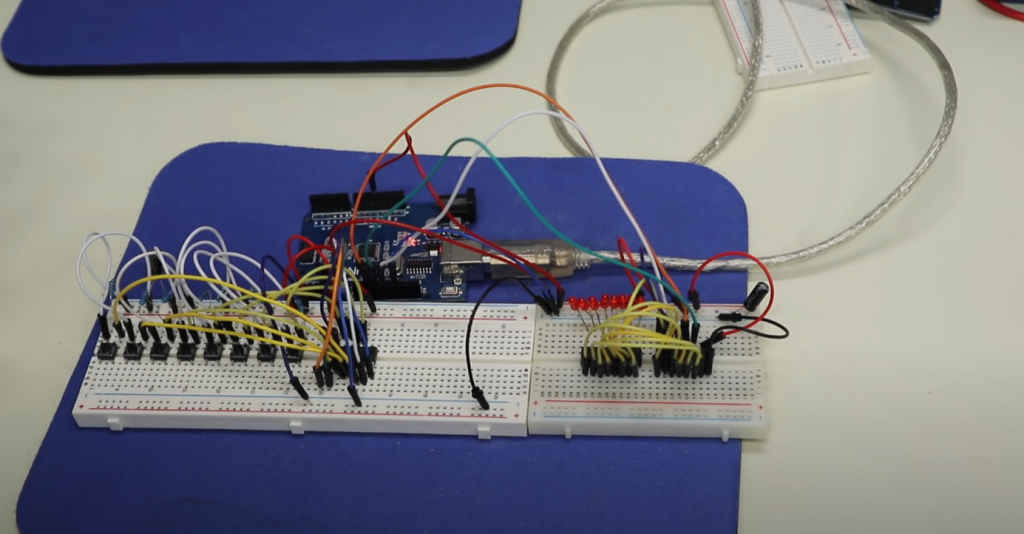
If you connect the shift registers in a cascade, there won’t be much change, although it will save you a lot of pins. This is because the chips are connected on pins Q7′ – DS, the second capacitor can not be connected.
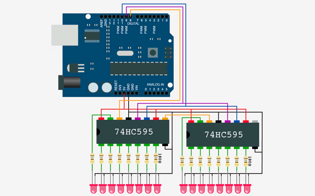
In the schematic, you can see that the orange wire connects to pin 9 of the first chip to pin 14 of the second chip. It remains to load the sketch to connect all 16 LEDs:
//Pin SH_CP
Int SH_CP = 10;
//In pin ST_CP
pin ST_CP = 9;
//DS pin
int DS = 8;

void setup() {
   // set the outputs SH_CP, ST_CP, DS
   pinMode(SH_CP, OUTPUT);
   pinMode(ST_CP, OUTPUT);
   pinMode(DS, OUTPUT);
}

void loop() {
  // loop around 16 LEDs
  for (int i = 0; i < 16; i++) { // Write to register registerWrite(i, HIGH); // Delay 0.5 s. delay(500); // Turning off the previous LED if (i > 0) {
       registerWrite(i - 1, LOW);
    }
    // turning off the last LED
    // ("previous" for the first one)
    else {
       registerWrite(15, LOW);
    }
  }
}

// method to send data into registers
void registerWrite(int num, int state) {
 // unsigned int is used to store the 16 bits
 unsigned int bitsToSend = 0;
 // 0b000000000000000
 // Initialize start of data reception
 digitalWrite(ST_CP, LOW);

 // Set a 1 in the corresponding bit
 bitWrite(bitsToSend, num, state);

 // The 16 bits must be divided into two bytes:
 // And write each byte to the corresponding register
 Byte register1 = highByte(bitsToSend);
 byte register2 = lowByte(bitsToSend);

 // Sequential data transfer to DS pin
 shiftOut(DS, SH_CP, MSBFIRST, register2);
 shiftOut(DS, SH_CP, MSBFIRST, register1);

 // Initialize the end of the data transfer.
 // The registers will apply voltage to the specified outputs
 digitalWrite(ST_CP, HIGH);
}
We can see that functions make the work with the registers much easier. These are functions responsible for placing a specific bit in a given position of the number – bitWrite, and functions lowByte and highByte, extracting the lowest and highest 8 bits from the transmitted number.
This completes the connection of the eight (in practice 16) LEDs. Again, only three pins of the Arduino microcontroller are used.


I never thought I would be using a shift register but when I was given the Arduino project to work on, it became apparent that it was necessary. I had no idea how they worked before but after some research and practice, I feel like an expert now.
A shift register is a chip that allows you to expand the number of pins on a microcontroller. This is incredibly useful if you need more digital outputs than your controller has natively. For example, the Arduino Uno only has 14 digital pins but with a shift register you can control up to 8 devices with just 3 pins.
I found working with the shift register to be very easy and straightforward. The hardest part was probably understanding the concept behind it and how it worked. But once I got my head around that, using it was a breeze.