
Today in this article, you will learn how to perform a three-phase AC voltage measurement with the Arduino. First, we will show you how to measure single-phase AC voltages and then measure three-phase AC voltages.
The developed system can measure AC voltages of any amplitude, display each phase voltage, perform LED indication of each phase voltage.
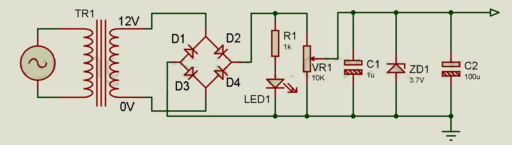
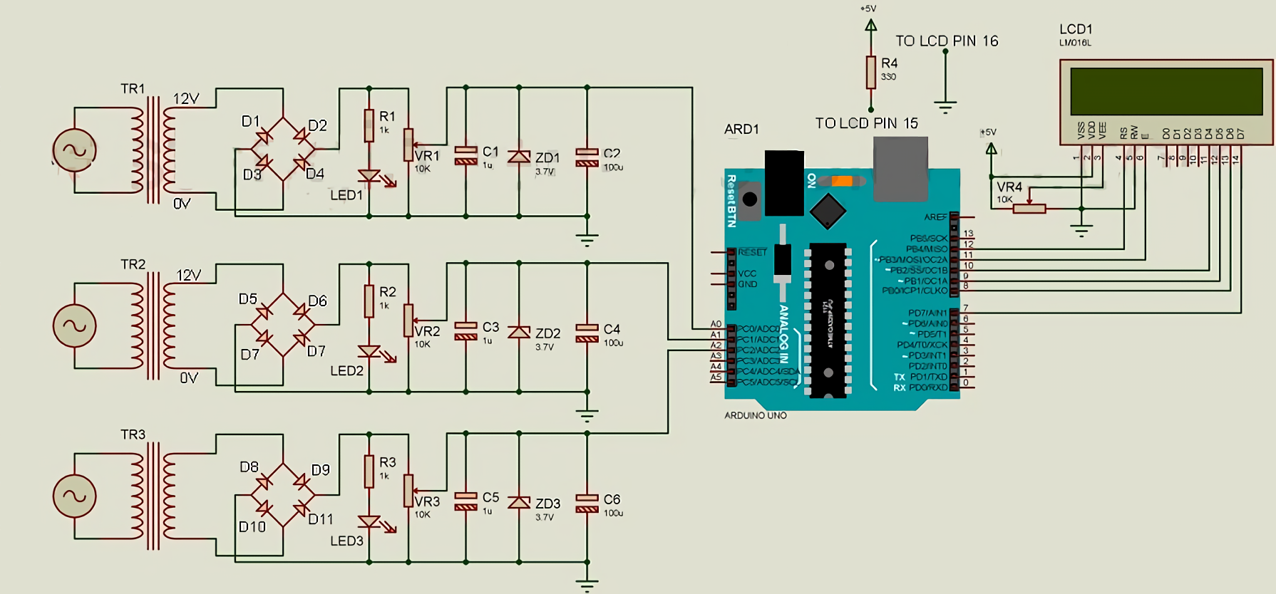
The operating principle of the system is as follows. The high AC input voltage is first converted to a lower AC voltage using a transformer and then rectified using a double half-period bridge rectifier. Next, the rectifier output voltage is fed to a voltage divider circuit, which lowers the rectified DC output voltage, and then the voltage is filtered and fed to a stabilizer. Finally, the output is provided to the analog pin input of the Arduino A0-A2.
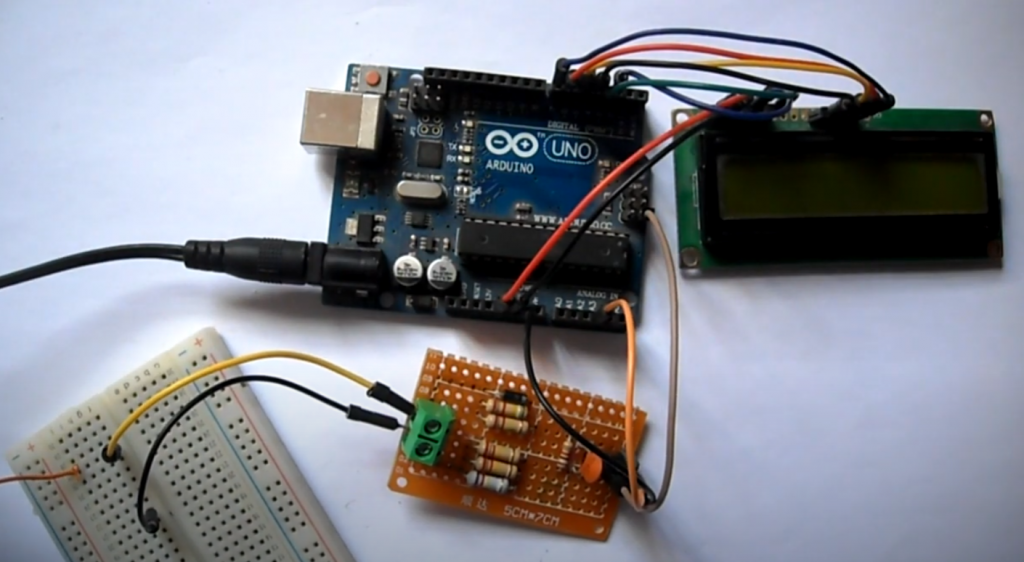
The circuit is elementary to understand and is designed using a transformer, a bridge rectifier, a stabilizer, an Arduino Uno, an LCD, and some other components like a resistor and capacitor, etc. For example, here is a circuit to measure one of the phase voltages.
The AC input voltage to be measured is fed to the primary side of transformer X1, which lowers the high input voltage (e.g., 220 VAC) to a low AC voltage (e.g., 12 VAC). The Arduino cannot measure the negative half-period as input, so we need to either cut or change the negative half-period to a positive half-period. To do this, we use a bridge rectifier.
The AC voltage (12 VAC) is rectified with four diodes (1N4001). The rectified voltage is fed to a voltage divider circuit designed with a variable resistor VR1. The two fixed terminals of the variable resistor are connected to the positive and negative terminals of the rectified output, as shown in the circuit diagram. The output is taken from the variable resistor VR1. The output voltage is then filtered using capacitors C1 and C2. A stabilitron is used here to protect the circuit, which trips when the input voltage exceeds 3.7V. This output voltage is now sent to the analog pin of the Arduino Uno A0.
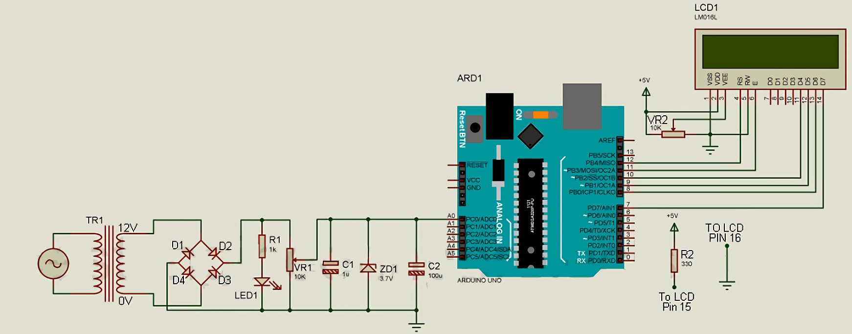
The Arduino measures this voltage and displays it on the LCD. The LCD is connected to the Arduino with higher-order data bits, i.e., only the higher-order data pin (D4 to D7) is used for communication between Arduino and the LCD. Data pins D4 to D7 are connected to the Arduino D10 to D7, respectively, as shown in the schematic diagram. Here the EN and RS pins are connected to Arduino D11 and D12, respectively. Vss, RW, and LCD LED pin is connected to GND, and VDD pin is connected to +5V. The VEE pin is responsible for the contrast control, and the supply voltage must be between VDD and VSS, so the VR2 potentiometer pin is connected to this pin. Finally, the LED+ pin of the LCD is connected to +5V via a current limiting resistor, as shown in the circuit diagram.
Now we have to calibrate. The code for the calibration is shown below.
int ACInput = A0;

//Setup function Start
void setup() {
  pinMode(ACInput, INPUT);
  Serial.begin(9600);
}

//Loop Function Start Here
void loop()
{
   int vrout = analogRead(ACInput);
   Serial.println(vrout);
   delay(500);
 }
The calibration procedure is as follows:
- Measure the AC line voltage with a multimeter (it doesn’t have to be 220 V, it can be 227 V).
- Adjust the variable resistor so that the output voltage at the stabilizer is constant and below 3.7V (say 2.66VDC).
- Load the calibration firmware on your Arduino and open the serial monitor.
It will display some value (say 545). Save the value because we need it for further calculations. Then, adjust the variable resistor to reach this value (545).
Now calculate the multiplier. For a 5 volt Arduino, the maximum value from the ADC will be 1023. Similarly, using the unitary method, we can calculate the voltage for the 1 division it shows: 1 = 5/1023 В. So for a value of 545 the division voltage = (5/1023) * 545 = 2.66 V. When the mains voltage is 227 VAC, the Arduino shows 2.66 V. Multiplier = 227 V / 2.66 V = 85.30. As a result, the program code for measuring single-phase AC voltage will be as follows.
#include <LiquidCrystal.h>
LiquidCrystal lcd(12, 11, 10, 9, 8, 7); //(RS,EN,D4,D5,D6,D7)
int Volt = A0; // For input of variable voltage

void setup() {
  pinMode(Volt, INPUT);
  lcd.begin(16,2);
  Serial.begin(9600);
}

//Loop Function Start Here
void loop()
{
  lcd.clear();
   int AcVolt = analogRead(Volt); // read analog input
   int AcVoltOut = (AcVolt * (5.0 / 1023))*93.67; // conversion to volts
   Serial.println(AcVoltOut); // display in serial monitor
   lcd.setCursor(0,0);
   lcd.print("AC Voltage");
   lcd.setCursor(0,1);
   lcd.print(AcVoltOut); // display
   delay(500);
 }
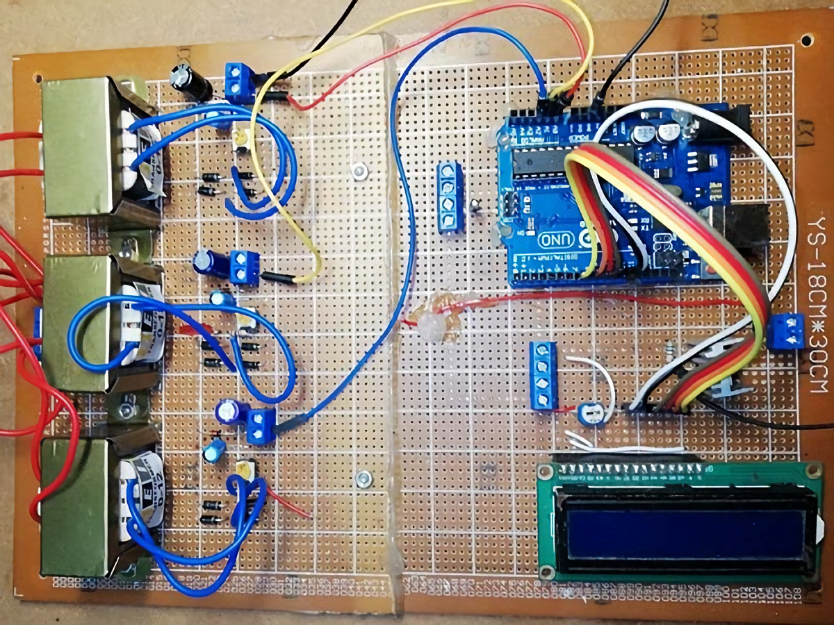
The circuit for measuring three-phase AC voltage is the same as for single-phase, only with two additional single-phase voltage measurement circuits.
The code for the three-phase voltage measurement program is as follows.
#include <LiquidCrystal.h>
LiquidCrystal lcd(12, 11, 10, 9, 8, 7); //(RS,EN,D4,D5,D6,D7)
int RPhase = A0; // For phase A
int YPhase = A1; // For phase B
int BPhase = A2; // For phase C

void setup() {
  pinMode(RPhase, INPUT);
  pinMode(YPhase, INPUT);
  pinMode(BPhase, INPUT);
  lcd.begin(16,2);
  Serial.begin(9600);
}

void loop()
{
  lcd.clear();
   int vrout = analogRead(RPhase); // Read phase A
   int vyout = analogRead(YPhase); // Read phase B
   int vbout = analogRead(BPhase); // Read phase C
   int RVolt = (vrout * (5.0 / 1023))*93.67; // converting phase A value into volts
   int YVolt = (vyout * (5.0 / 1023))*93.67; // Conversion of B phase value to volts
   int BVolt = (vyout * (5.0 / 1023))*93.67; // Conversion of phase C value into volts
   Serial.println(RVolt); // Output phase A to the serial monitor
   Serial.println(YVolt);// Output phase B to the serial monitor
   Serial.println(BVolt); // Display phase C in the serial monitor
   lcd.setCursor(0,0);
   lcd.print("A B C ");
   lcd.setCursor(0,1);
   lcd.print(RVolt); // Display phase A on the display
   lcd.setCursor(4,1);
   lcd.print(YVolt); // Display phase B
   lcd.setCursor(8,1);
   lcd.print(BVolt); // Display phase C
   delay(500);
    }
 }
Final Thoughts
In conclusion, measuring AC voltage using an Arduino can be a simple and cost-effective solution for a variety of applications. By following the steps outlined in this guide, you can learn how to accurately measure AC voltage with an Arduino and use that data to drive a range of different projects and systems. Whether you are a beginner or a seasoned Arduino user, this guide provides a great introduction to the basics of AC voltage measurement and how to incorporate it into your own projects. So go ahead and give it a try – you might be surprised at what you can achieve!


Will this circuit able to monitor low ac voltages such as range of 1-50v
You should check it.
I recently decided to measure AC voltage with my Arduino and it was a great experience. I’ll tell you how I did it and what I learned.
First, I gathered my supplies. I needed an Arduino, a breadboard, some jumpers, and an AC-to-DC adapter. I also downloaded the Arduino IDE and the AC Voltage Measurement sketch.
Next, I set up my circuit according to the diagram in the sketch. Then, I connected the Arduino to my computer and uploaded the sketch.
Finally, I ran the sketch and saw that it was measuring the voltage correctly! I was really happy with how easy it was to do this project.