
In this tutorial, we simulate a theremin musical instrument’s action: we change the sound’s height in a non-contact way, closing the photoresistor more or less from the light.
The original instrument was invented back in 1920 by Leon Theremin, a man with a difficult and intense fate. And now we have the opportunity to reproduce the invention with the help of simple electronics.
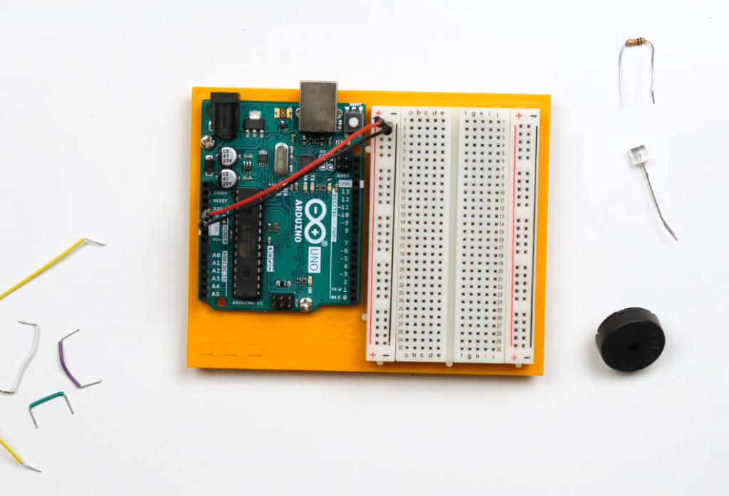
List of Details
- 1x Arduino Uno board
- 1x unsolderable breadboard
- 1x piezo squeaker (a capacitor that sounds when charging and discharging)
- 6x male wires
- 1x 10 kOhm resistor
- 1x photoresistor
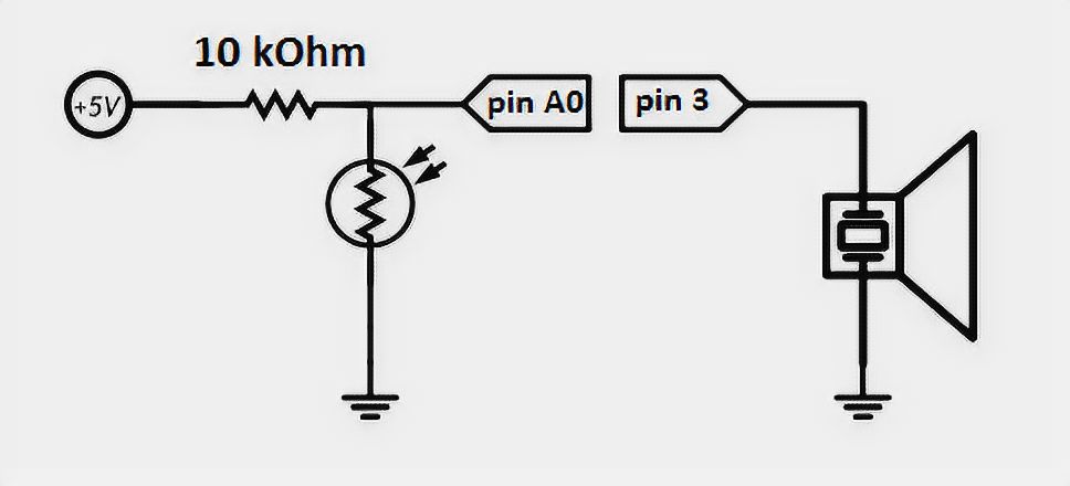
Circuit Diagram
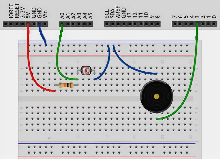
The Scheme on the Layout
Pay Attention
- In this diagram, we use a new rated resistor, look at the marking table to find a 10 kOhm resistor, or use a multimeter.
- The polarity of the photoresistor, like a conventional resistor, does not play a role. It can be installed on either side of the photoresistor.
- In this exercise, we collect a simple version of the piezodynamic circuitry.
- The piezo’s polarity does not matter: you can connect any of its legs to the ground, any of them to the microcontroller port.
- On Arduino Uno, the use of the tone function prevents PWM usage on ports 3 and 11. However, you can connect it to one of the following ports.
- Remember how the voltage divider is arranged: the photoresistor is placed in position R2 – between analog input and ground. This is how we get a resistive photosensor.
Sketch
// give names for piezo pins and photo -
// Light Dependent Resistor or simply LDR)
#define BUZZER_PIN 3
#define LDR_PIN A0

void setup()
{
  // pin with a piezo - exit...
  pinMode(BUZZER_PIN, OUTPUT);

  // ...and all other pins are inputs initially,
  // every time the microcontroller is powered up or reset.
  // Therefore, we don't really need to
  // configure LDR_PIN to enter the login mode: it is already there
}

void loop()
{
  int val, frequency;

  // read the illumination level in the same way as for
  // potentiometer: as a value from 0 to 1023.
  val = analogRead(LDR_PIN);

  // calculate the frequency of the squeaker in hertz (note),
  // using the projection function (English map). It displays
  // value from one range to another, building the proportion.
  // In our case [0; 1023] -> [3500; 4500]. This is how we will get
  // frequency from 3.5 to 4.5 kHz.
  frequency = map(val, 0, 1023, 3500, 4500);

  // make the pin with the squeaker "vibrate," i.e., sound
  // (English tone) at a given frequency of 20 milliseconds.
  // At next loop passes, the tone will be called again and again,
  // and in fact, we will hear a continuous sound with a tonality that
  // depends on the amount of light hitting the photoresistor
  tone(BUZZER_PIN, frequency, 20);
}
Code Explanation
- The
map(value, fromLow, fromHigh, toLow, toHigh)function returns an integer value from the[toLow, toHigh]interval, which is a proportional display of the value content from the[fromLow, fromHigh]interval. - The map’s upper limits do not have to be larger than the lower ones and may be negative. For example, you can display the value from the interval [1, 10] in the interval [10,-5].
- If a fractional value is formed in calculating the
mapvalue, it will be discarded, not rounded. - The
mapfunction won’t discard values outside the specified ranges and scale them by the specified rule. - If you need to limit a lot of acceptable values, use the
constrain(value, from, to)function, which will return them:
–value, if this value falls into the range[from, to].
–from, if thevalueis less than it
–to, if thevalueis greater than it - The
tone(pin, frequency, duration)function causes the piezo squeaker connected to the pin port to produce a sound with frequency hertz over a duration of milliseconds. - The duration parameter is optional. If it is not transmitted, the sound will turn on forever. To turn it off, you will need the
noTone(pin)function. It needs to pass the port number with the squeaker to be turned off. - Only one squeaker can be operated at a time. If you call tone for another port during the sound, nothing will happen.
- Invoking tone for an already sounding port will update the frequency and duration of the sound.
Arduino Theremin: Comparison of Various Indicators
This table presents a comparison of various indicators related to Arduino Theremin, a musical instrument that produces sound based on the proximity of the player’s hand to the sensors. The indicators considered here are essential for understanding and building an Arduino Theremin project. The table below provides a concise overview of the compared aspects.
| Indicator | Description | Traditional Theremin | Arduino Theremin |
|---|---|---|---|
| Principle of Operation | The underlying concept behind sound generation | Electromagnetic fields | Ultrasonic distance sensing |
| Complexity | Level of technical difficulty to build | High | Medium |
| Cost | Approximate budget required | Expensive | Affordable |
| Components | Key elements used | Vacuum tubes, antennas | Arduino board, ultrasonic sensor |
| Sound Generation | Method of producing audio | Analog | Digital |
| Range | Playable pitch and volume range | Wide | Limited |
| Tuning | Process to adjust the pitch and tone | Manual calibration | Programmable tuning |
The table presents a comparison of various indicators between traditional Theremin and Arduino Theremin.
- The “Principle of Operation” indicates the underlying concept behind sound generation, where traditional Theremin relies on electromagnetic fields, while Arduino Theremin uses ultrasonic distance sensing.
- The “Complexity” factor suggests that building a traditional Theremin is considered high in technical difficulty, whereas the Arduino Theremin falls into the medium complexity range.
- “Cost” highlights that the traditional Theremin can be quite expensive to construct, whereas the Arduino Theremin is more budget-friendly and affordable.
- “Components” compares the key elements used in both Theremin types, with traditional Theremin employing vacuum tubes and antennas, while the Arduino Theremin utilizes an Arduino board and an ultrasonic sensor.
- “Sound Generation” highlights the difference between analog sound generation in traditional Theremins and digital sound generation in Arduino Theremins.
- “Range” denotes the playable pitch and volume range, where traditional Theremins typically have a wide range, whereas Arduino Theremins might have a more limited range.
- “Tuning” explains the process to adjust the pitch and tone, where traditional Theremins require manual calibration, while Arduino Theremins offer programmable tuning, making it more flexible for customization.
This table serves as a helpful comparison guide for individuals interested in Arduino Theremin projects, providing a quick overview of the key differences between traditional and Arduino-based implementations.
Useful Video: How to Build an Arduino Theremin
Final Words
The Arduino Theremin is a fascinating project that innovatively combines music and technology. By following the steps outlined in this tutorial, anyone can build their own theremin and experiment with creating unique sounds. The versatility of the Arduino platform makes it an ideal choice for those interested in exploring the possibilities of electronic music. Whether you are a musician or a hobbyist, building your own Arduino Theremin is a fun and rewarding experience that will open up new avenues of creativity. So why not give it a try and see what kind of musical magic you can create with your own hands?


