A typical wiring diagram of any microcontroller contains a number of components and circuits that ensure its normal functioning. The combination of these components is called a microcontroller wrapper. This publication is dedicated to the bundling functions and their peculiarities when using the AVR microcontroller ATmega328P.
ATmega328P Pinout
Before we start to look at the pinout of the ATmega328P, I think it is necessary to describe the pinout of the ATmega328P. When we work with Arduino boards, we don’t think about the correspondence of the microcontroller’s physical pins used in the Arduino IDE. When it comes to a single microcontroller, you always need to have its pinout at hand. So it is a good idea to keep the pinout:

Connecting the Power
The power supply voltage is connected to the pins VCC and GND of the microcontroller and must not exceed the datasheet’s value. For the ATmega328P, the upper limit of the recommended supply voltage is 5,5V, the absolute maximum is 6V.
It is recommended to install a 0.1MF ceramic capacitor between VCC and GND to suppress high-frequency interferences. It should be placed as close as possible to the microcontroller’s supply pins to minimize the parasitic inductance and the resistance of the supply wires.
The ATmega328P has a dual power supply: VCC and GND (pins 7 and 8) are used to power the digital circuits of the microcontroller; AVCC and GND (pins 20 and 22) are used to power the analog to digital converter. Even if you are not going to use the ADC, you have to power it: connect VCC to AVCC and digital ground to analog. If you plan to use the ADC, a filter should be added to the power supply circuit to reduce noise. The datasheet is recommended to connect AVCC to VCC with a 10µH inductance and GND with 0.1µF capacitance. However, this recommendation is not implemented even in the Arduino boards, and the AVCC pin is simply connected to VCC.
The Reset Pin and the Reset Button
The Reset pin is used to generate a reset signal on the microcontroller. All I/O registers take their initial values during reset, and the command located in the reset vector (at address zero) is executed. Usually, this is a jump to the program start address. But, if the user program does not use interrupts, it can be located directly at address zero.
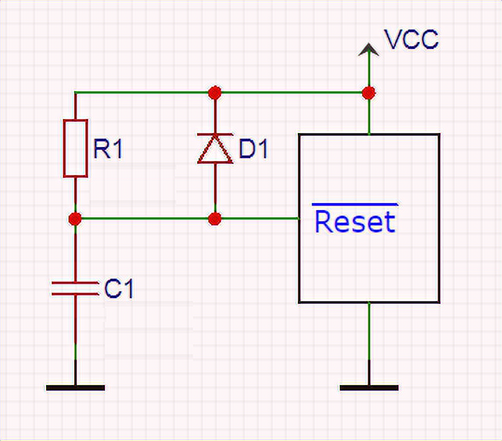
Initial Reset Scheme
The bundling for previous microcontroller models necessarily included an initial reset circuit consisting of a resistor and a capacitor, which ensured that the reset input is rising gradually when the power was turned on. This is how the initial reset of the microcontroller was done. Nowadays, every modern microcontroller probably has a Power-on-Reset circuit. An external circuit may be required if there are special requirements for the reset pulse duration (in case of a slow rise of the supply voltage).
The resistor and capacitor values may differ from the diagram’s values and depend on the required reset pulse duration.
The Reset and the Protection Against Unintentional Reset
Another thing to pay attention to is the stabilization of the high-level signal at the Reset input to prevent the microcontroller from resetting unintentionally. In my article about pull-up resistors, I mentioned the problems that occur when the digital input is not connected to power or ground: electromagnetic interference causes a change of signal level on this input. When polling this input, the microcontroller will randomly register a high and a low signal level. In the case of the Reset input, this will cause an unintentional reset. This problem can be solved by adding a pull-up resistor that ensures that the Reset input is at the right level (in the case of the AVR, it is high).
The demand for pull-up resistors both for the Reset input and for the normal I/O lines led to the addition of these in the microcontrollers. The ATmega328P has its own pull-up resistor on the Reset input of 30-60kOhm (the specific value from this range is set at the factory during calibration). And here, the question often arises: whether you need an external pull-up resistor at the Reset input or whether you can do with the internal one. It all depends on the specific situation and conditions in which the microcontroller will be working: for amateur, “domestic” projects, maybe a built-in resistor will be enough; for devices designed for industrial use in unfavorable conditions, the built-in resistor may be insufficient. This is what is called a weak pull-up. In such cases, the digital input is pulled up by an external resistor of several kOhms.
Often the pull-up resistor alone is not enough, and a capacitor is added to the circuit for extra noise protection. The Reset input of AVR microcontrollers has its own low-pass filter. An external capacitor between Reset and ground is extra protection. However, it must not be added to the circuit if in-circuit programming with PDI or DebugWIRE is intended.
Unlike the general-purpose pins, which have protection diodes to both ground and power, there is a single diode for the Reset input – to ground. This is because Reset is used for high voltage programming when a 12V signal is applied to it. Therefore if the microcontroller has to work in interference from electrostatic discharges (ESD – Electrostatic Discharge term is used in technical documentation) and if you do not plan to use a high voltage programmer. It is recommended to add an external diode between the Reset pin and the power line to the circuit.
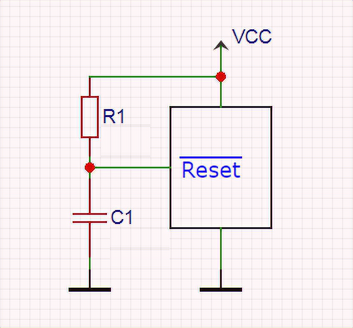
Taking all this into account, the recommended scheme for the Reset pin is as follows:
And in the end, you can do without external components at all if you just connect Reset to the power line. But in this case, you can not add a reset button, and you will lose the on-chip programming.
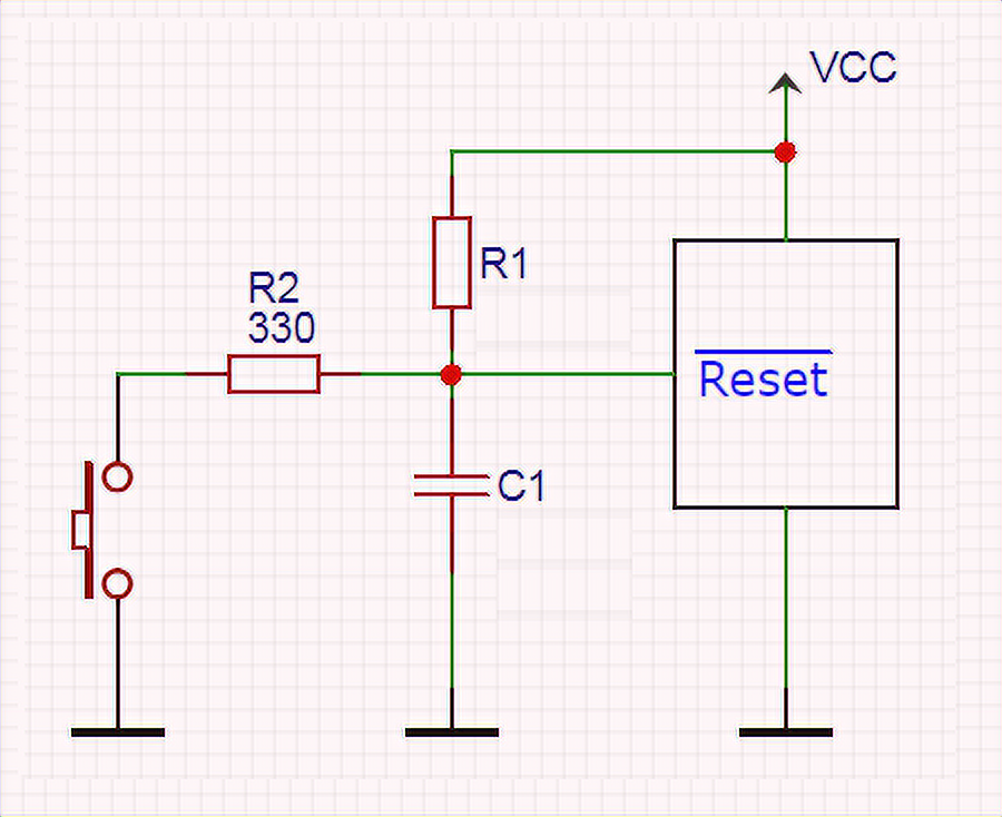
Reset Button
Suppose you pull up the Reset input to the power supply to protect the microcontroller from an accidental reset (with a built-in resistor or an external one for a stronger pull-up). In that case, it has to be shorted to the ground to reset when you press the button. Nothing simpler – add a button between the Reset input and ground. Suppose the Reset pin winding contains a capacitor like in the above schematic. In that case, the Microchip developers recommend adding a resistor of about 330 ohms to the circuit to prevent it from being shorted through the button (which can cause noise):
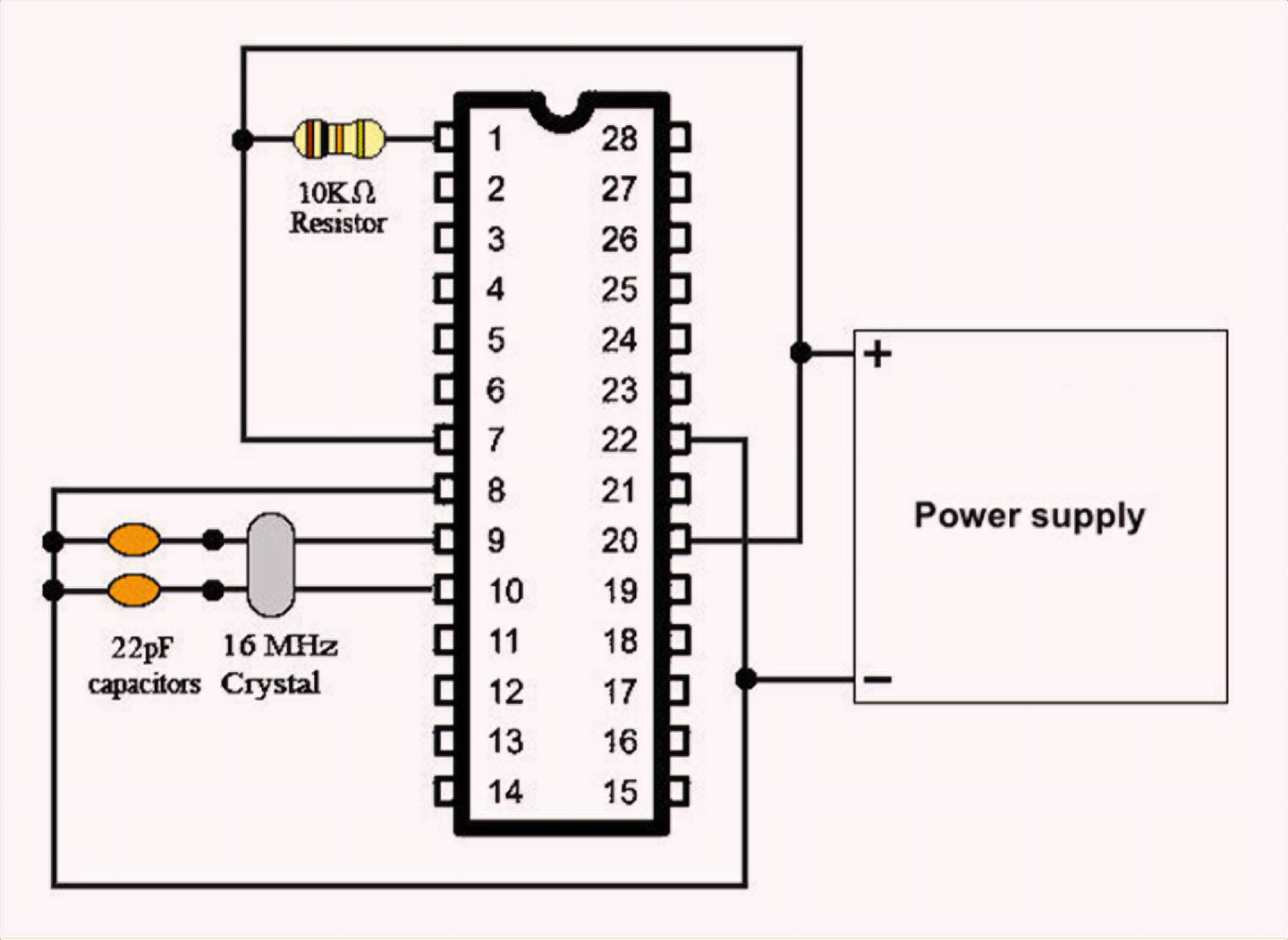
Connecting the Resonator
Quartz or ceramic resonator makes the built-in clockwork. The resonator is connected to pins XTAL1, XTAL2 of the microcontroller. Thus, ceramic capacitors are added to the circuit, the value of which is selected in accordance with the manufacturer’s recommendations of the resonator or the microcontroller to make it stable. So in the datasheet of the ATmega328P for resonators at 400kHz and higher, it is recommended to use capacitors with a rating of 12…22pF:
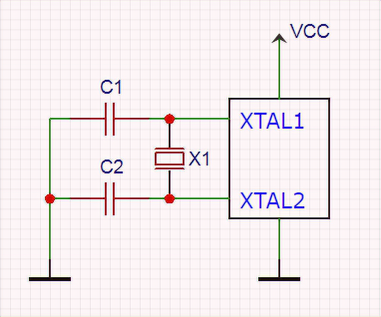
If you use a 32.768kHz resonator, you can use internal capacitors and connect them to XTAL1 and XTAL2 by setting the fuses CKSEL.
When clocking from an internal RC oscillator, there is no need for an external resonator and matching capacitors.
Conclusion
So most of the components that make up a typical integrated circuit are already present in today’s microcontrollers. However, they can be insufficient for stable operation in a harsh environment, and additional measures have to be taken. Again it is hard to know what to expect and how to guarantee the success of the solution. So the best recommendation is always to test the circuit under realistic conditions.