
Arduino Attiny85 board from the ATtiny series is a junior line of Atmel microcontrollers, which has cut down compared to the ATmega chips.
The official family of Arduino boards has been very extended by third-party manufacturers and enthusiasts in microcontroller programming. To understand why this has happened, you need to understand what an Arduino is.
 ATtiny85 is a low-power CMOS 8-bit microcontroller based on the AVR enhanced RISC architecture. The device achieves a throughput of 20 MIPS at 20 MHz and operates between 2.7-5.5 volts.
The platform is a board with a microcontroller and the necessary interconnects, but the very essence is a set of libraries and the Wiring language, which allows you to create sketches simply and clearly.
Characteristics of ATtiny Boards
In the table below, we list the main characteristics of ATtiny boards:
| ATtiny 44 | ATtiny 84 | ATtiny 45 | ATtiny 85 | Note | |
| Max frequency, MHz | 8 | 8 | 8 | 8 | From the internal generator |
| RAM, bytes | 256 | 512 | 256 | 512 | – |
| Flash, Kb | 4 | 8 | 4 | 8 | – |
| I/O outputs | 11 | 11 | 5 | 5 | RESET do not count |
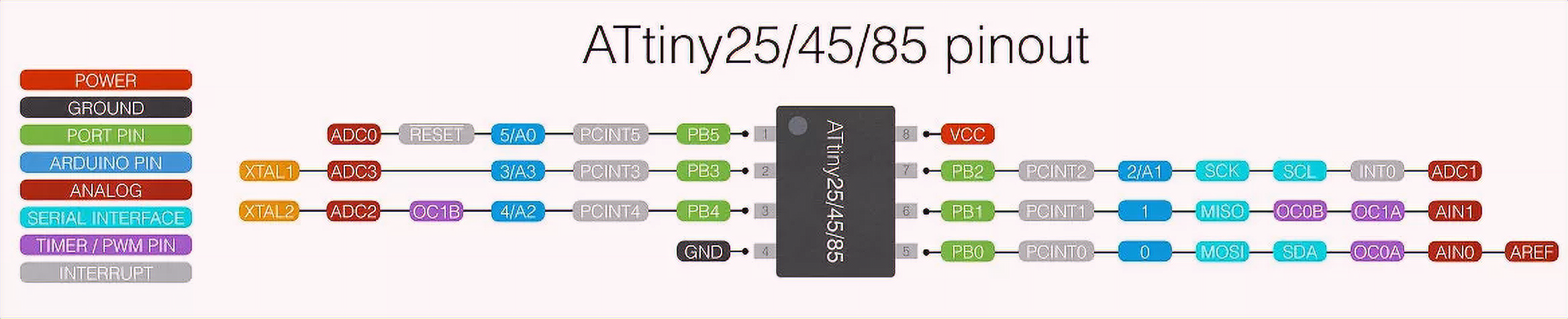
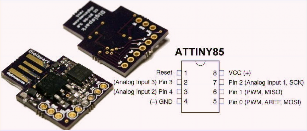
ATtiny85 Pinout
The ATtiny85 pinout can be seen below. Click to enlarge the schematic:
Another circuit you might find useful:
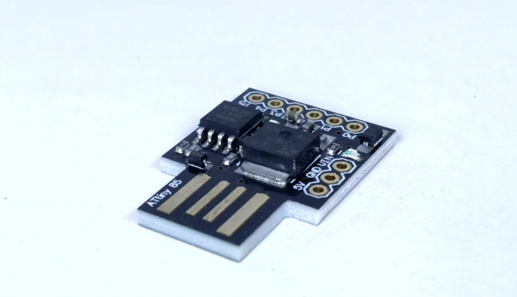
Digispark Board with Arduino Attiny85
Compatible boards can both outperform and be smaller than standard Arduino boards, as mentioned above. A great example of such a board would be the Digispark.
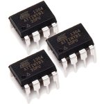
The characteristics of the board are quite modest. It comes with a microcontroller prepared to work, Arduino ATtiny85 – it is presented in an eight-legged SOIC package or a larger size – DIP8. The specifications are quite unassuming:
- the permanent memory is 8Kb, for program code and 512 for executable code;
- since there are only 8 pins available, subtract the two-plus and minus power, and you have 6 digital pins, of which 4 are ADC and 2 PWM;
- only a hardware interrupt is available;
- the controller operates at frequencies from 1 to 20 MHz;
- depending on the specific chip, the supply voltage varies from 1.8 to 5.5 volts;
- in power saving mode consumes a negligible current of 0.1 µA at the lowest supply voltage of 1.8 volts.
The original Digispark has an interesting design. You don’t need to use a micro USB cable or USB-UART to flash it. The board is wired in such a way that you can program the microcontroller just by plugging it into a USB port on your computer.
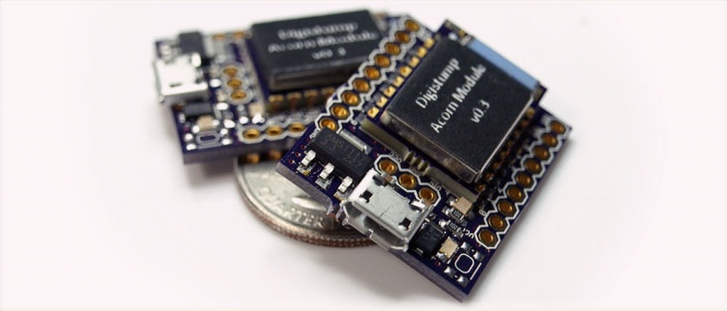
The board is small and very easy to assemble, and for beginners, it does not take long. We will tell you how to assemble the Digispark clone with your own hands later on.
What You Should Know Additionally
The language Wiring is not a programming language. It is a C language overlay. The code is easy to use and simple, thanks to the many libraries for working with peripherals and delays. The latter is specified in milliseconds or microseconds, which was not so obvious before, and in assembler, you had to count the number of clock cycles of the microcontroller and then make useless calculations to form the idle time of the system.
An easy-to-understand language and Arduino IDE were invented to simplify this process. However, many amateurs do not stop there and move on to the level of C language.
The fact is that the standard port access, read and write commands take quite a long time to execute using the Arduino. Therefore you can address them directly and speed up the board dozens of times, where necessary, and PWM on the Arduino runs at low frequencies, which is not a good sign, and in C, again, everything is several times faster.
About the Features of the Development Environment
Arduino IDE has a built-in set of boards and microcontrollers that you can work with; it’s based on the classic AVR programmer, by the way, it allows you to address the device with C commands.
However, it is not always convenient and rational to use the proposed microcontrollers. You must agree that it is stupid to take a board with a couple of dozen pins to work with one sensor and one actuator, which can be:
- servo actuator;
- transistor;
- LED;
- solenoid, etc.
For this reason, third-party developers have created a number of compatible boards. It is possible to work with them through the Arduino IDE, using simple built-in language commands. Loaders and command libraries have been rewritten for this purpose.
How to make a very small Arduino with your own hands?
The Arduino board itself, the UNO version, for example, can be used as a universal programmer. You can easily program other AVR and non-AVR family ICs with the Arduino ATtiny2313. The Attiny series itself, as you can see from the name, is a junior Atmel microcontroller family with chips cut down compared to ATmega.
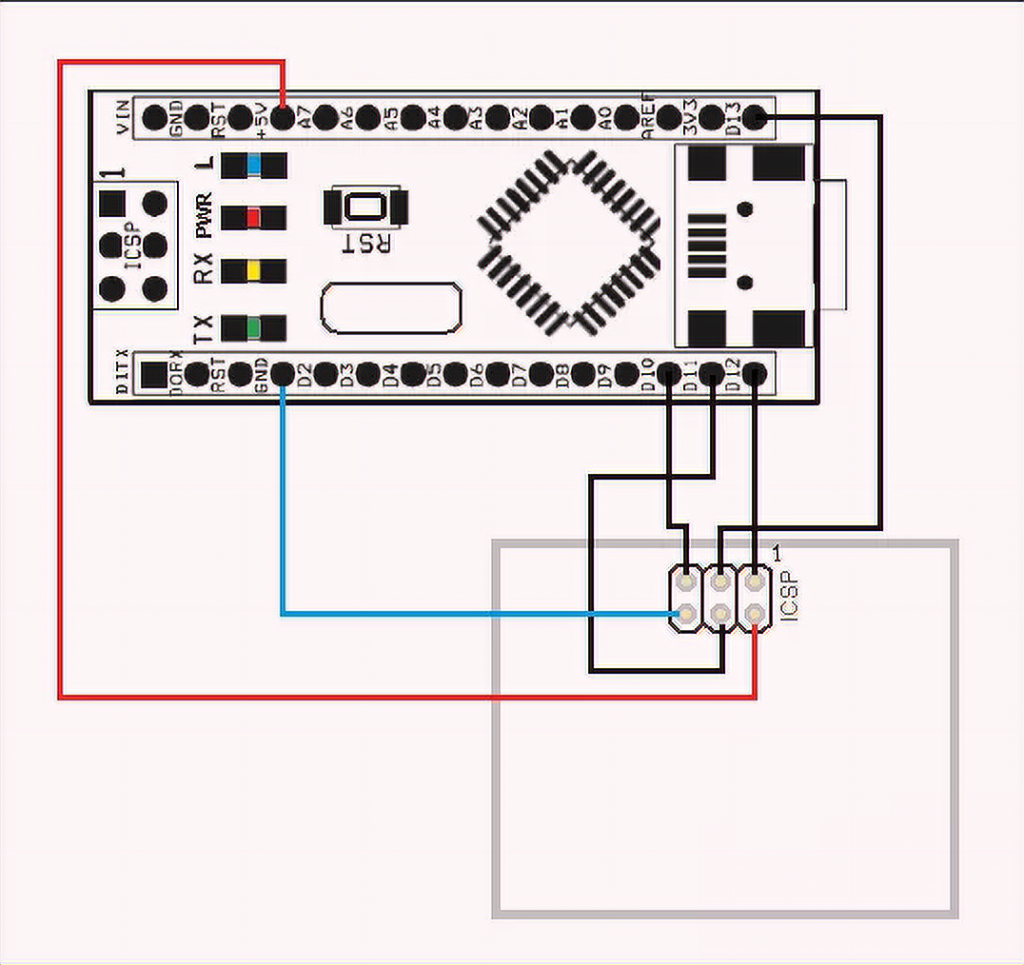
The picture shows an example of flashing an Arduino board with another Arduino board in case the microcontroller from the first one fails when you need to flash the boot loader into it.
Arduino ISP is a project that will turn your board into a programmer. For this, you need to load a sketch into the UNO board and use it for the firmware.
The term ISP itself stands for “in-system programming”, that is, flashing the chip already in the directly assembled circuit – this technique is used not only in amateur designs but also for correcting the software of ready-made blocks of industrial production and household appliances.
The firmware that will turn your Arduino into an ISP programmer comes in the Arduino IDE example kit. Connect your board to your computer and select File-examples-Arduino ISP. After that, add the sketch to the Arduino.
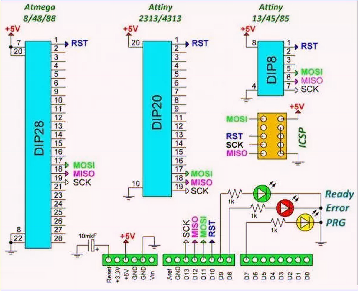
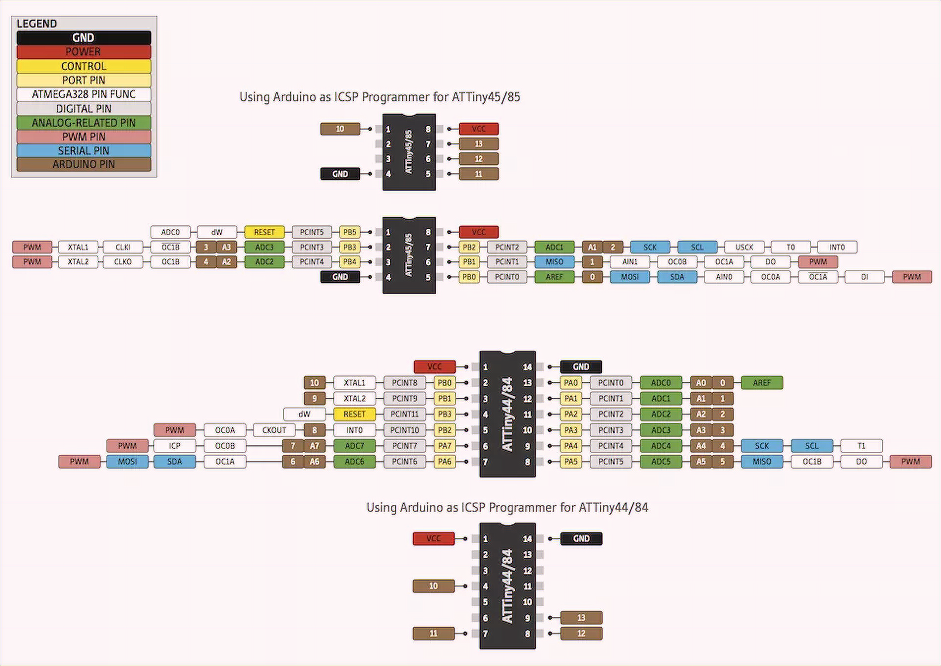
The picture shows the pin assignments of the Arduino and their location on the controllers in DIP cases. Connect the same pins on the microcontroller and the Arduino for flashing.
If you want, you can repeat your predecessors’ experience and make such a shield for UNO.
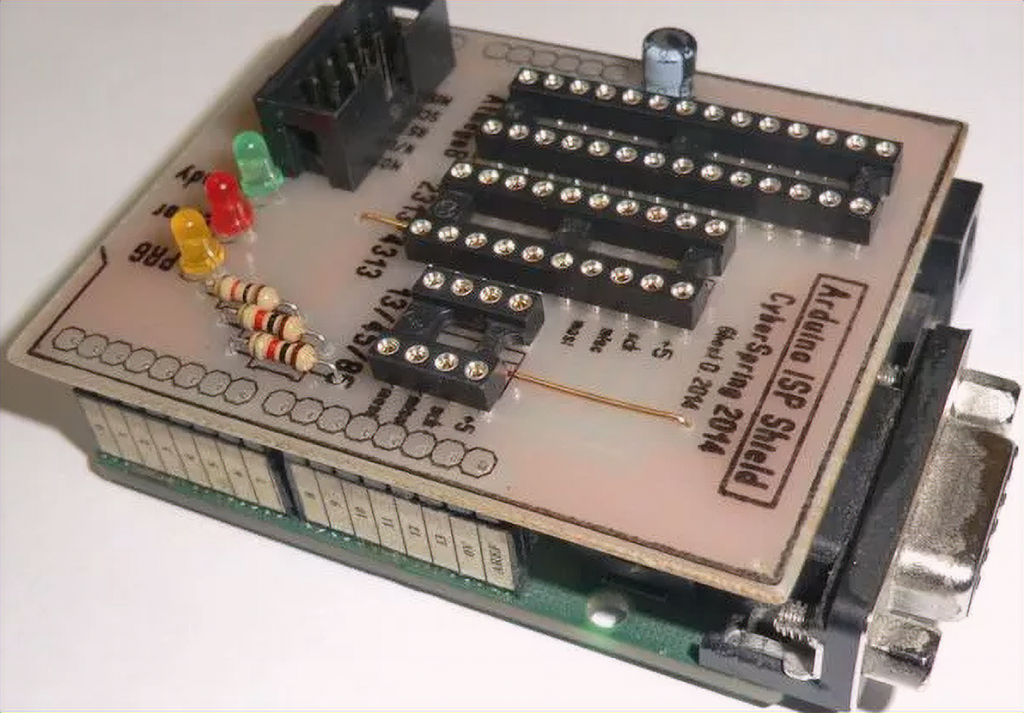
Here is the printed circuit board.
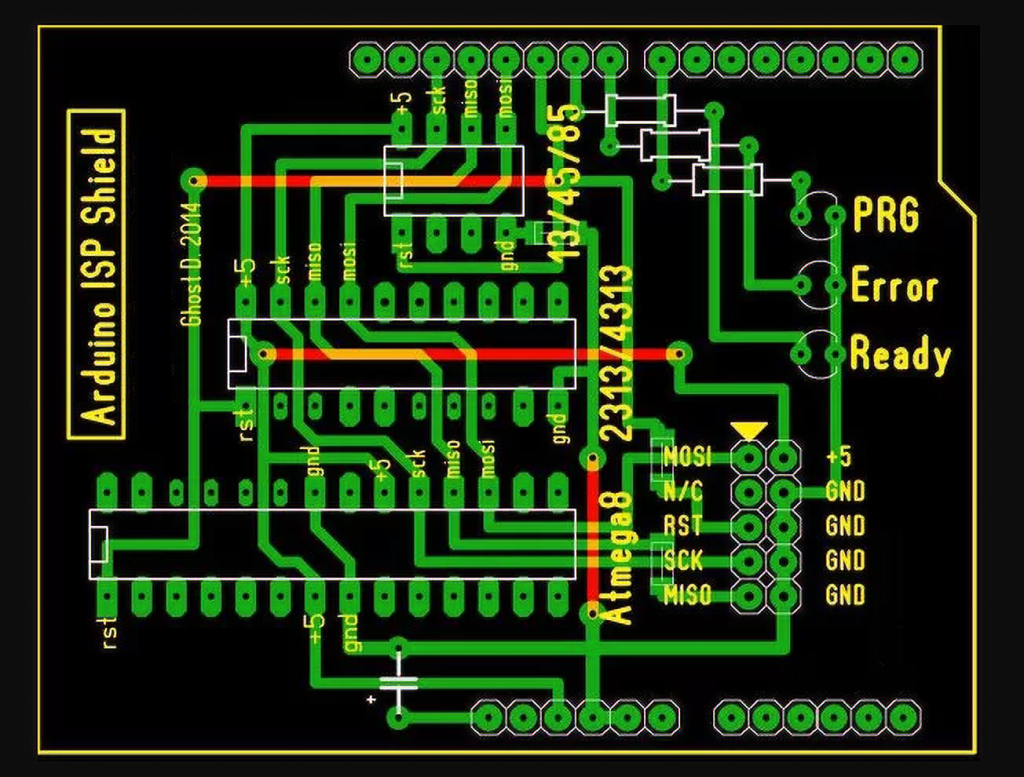
An explanation is unnecessary – just be creative and put it on the printed board.
To flash ATtiny with the Arduino IDE, you must first add libraries to support them. The only ATmega is supported as standard. Add the hardware folder in the directory C:\Users\*user name*\Documents\Arduino\ and in it the folder tiny from the archive, which can be found here.
After that, in the tiny folder, find the file Prospective Boards.txt and delete the first word “Prospective” from its name. Don’t forget to choose the “Arduino ISP” programmer.
When you flash attiny code will be easier than in UNO, some functions are truncated and available to you:
pinMode()
digitalWrite()
digitalRead()
analogRead()
analogReference(INTERNAL) / (EXTERNAL)
shiftOut()
pulseIn()
analogWrite()
millis()
micros()
delay()
delayMicroseconds()
What do we get?
You get a digispark analog, but it’s reduced to the size of a single chip; solder the peripherals, and you’re ready to go! You can make a cheap Arduino ATtiny13 with 1024 bytes of memory for the simplest blinkers and sensors.
Such miniature devices will save space and money when assembling. The fact is that for the price of a cheap Arduino nano, you can buy several ATtiny13, and you can program them with simple commands without learning C.


Thank you very much for this article. It helped me a lot with programming ATmega8-328 and ATtiny on Arduino. I will continue to follow your work on this site. Greetings from Czech Republic.