
A capacitor is a small “battery” that quickly charges when there is a voltage around it and discharges quickly back when there is not enough voltage to hold a charge.
The main characteristic of a capacitor is capacitance. It is signified by the symbol C, and its unit of measure is the Farad. The greater the capacitance, the more charge the capacitor can hold at a given voltage. Also, the higher the capacitance, the lower the charging and discharging rate.
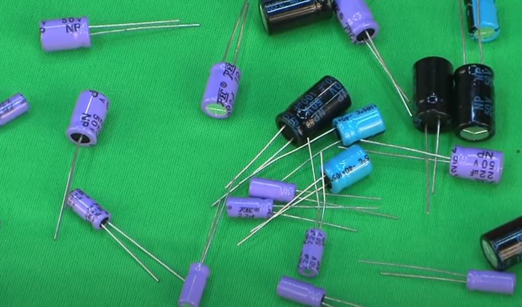
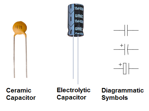
Typical values used in microelectronics range from tens of picofarads (pF, pF = 0.000000000001 F) to tens of microfarads (μF, μF = 0.000001 F). The most common types of capacitors are ceramic and electrolytic. Ceramic capacitors are smaller in size and usually have a capacity of up to 1 μF; they do not care which of the pins is connected to the plus and which to the minus. Electrolytic capacitors have capacities from 100 pF, and they are polar: a specific contact must be connected to the plus. The leg corresponding to the plus is made longer.
A capacitor is two plates separated by a dielectric layer. The plates accumulate a charge: one positive, the other negative; thereby a voltage is created inside. An insulating dielectric prevents the internal voltage from turning into an internal current that would equalize the plates.
Charging and Discharging
Consider such a circuit:
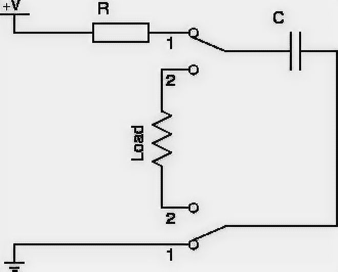
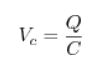
As long as the switch is in position 1, voltage is created on the capacitor – it is being charged. The formula calculates the charge Q on the plate at a certain point in time:
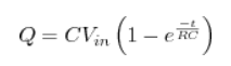
C is capacity, e is the exponent (constant ≈ 2.71828), t is the time since charging began. The charge on the second plate is always exactly the same, but with the opposite sign. If the resistor R is removed, only a small resistance of the wires remains (it will become the value of R), and the charge will be very fast.
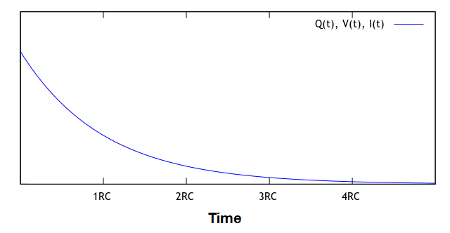
Plotting the function on the graph, we get the following picture:
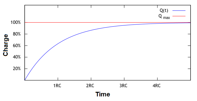
As you can see, the charge does not grow uniformly but inversely exponentially. This is because as the charge accumulates, it creates more and more reverse voltage Vc, which “resists” Vin.
It ends with Vc becoming equal in value to Vin, and the current stops flowing at all. At this point, the capacitor is said to have reached the equilibrium point. The charge at this point reaches a maximum.
![]()
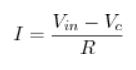
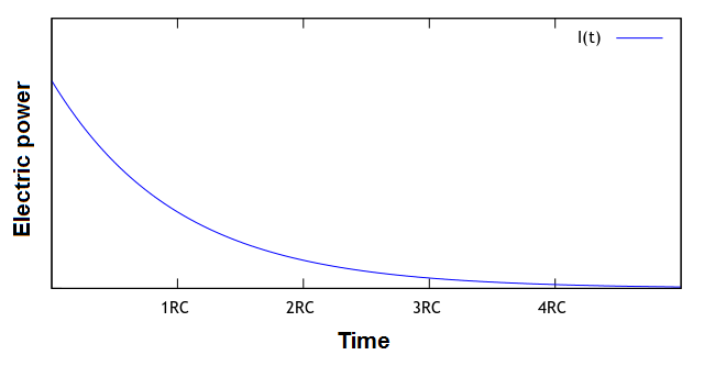
Recalling Ohm’s Law, we can depict the dependence of the current in our circuit when the capacitor is charged.
Now that the system is in equilibrium let’s put the switch in position 2.
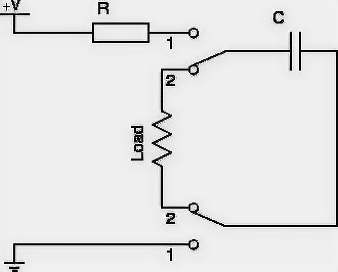
The capacitor plates have charges of opposite signs. They create a voltage – there is a current through the load. The current will go in the opposite direction compared to the direction of the power supply. A discharge will also happen in the opposite direction: at first, the charge will be lost quickly, then, with the drop in voltage created by it, it will be slower and slower. If Q0 is defined as the charge that was initially on the capacitor, then:
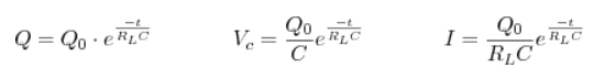
These values on the graph are as follows:
Again, after some time, the system will come to rest: all charges will be lost, the voltage will disappear, and the current will stop flowing.
If you use the switch again, everything will start in a circle. So the capacitor does nothing but opens the circuit when the voltage is constant; and “works” when the voltage changes abruptly. This is its property, which determines when and how it is used in practice.
Applications in Practice
Among the most common in microelectronics are these patterns:
- Bypass capacitor (bypass cap) – to reduce supply voltage ripples.
- Filter capacitor (filter cap) – for separation of constant and variable voltage components, for signal isolation.
Bypass Capacitor
Many circuits are designed to provide a constant, stable power supply. For example, a 5-volt power supply is supplied by a power supply. But there is no perfect system, and if the current consumption of a device suddenly changes, for example, when a component is turned on, the power supply does not have time to “react” immediately, and there is a short-term drop in voltage. Besides, in cases where the wire from the power supply to the circuit is long enough, it begins to act as an antenna and also introduces unwanted noise into the voltage level.
Usually, the deviation from the ideal voltage does not exceed a thousandth of a volt, and this phenomenon is absolutely insignificant when it comes to power, for example, LEDs or an electric motor. But in logic circuits, where switching of the logical zero and logical one takes place on the basis of small voltage variations, supply noise can be mistaken for a signal, leading to incorrect switching, which, in a domino effect, puts the system in an unpredictable state.
A bypass capacitor is placed directly in front of the circuit to prevent such failures.
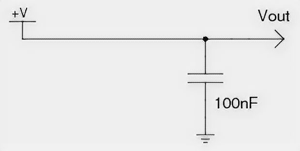
At times when the voltage is full, the capacitor charges to saturation and becomes a reserve charge. As soon as the voltage level on the line drops, the bypass capacitor acts as a fast battery, giving up the previously accumulated charge to fill the gap until the situation is normalized. This helps to the main power supply happens a huge number of times every second.
To put it another way: the capacitor separates the AC component from the DC voltage, and bypassing it through, it takes it from the power line to the ground.
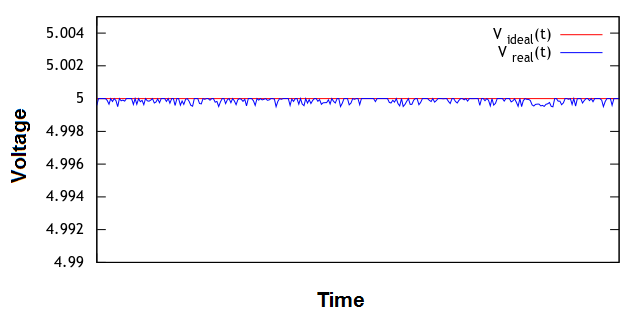
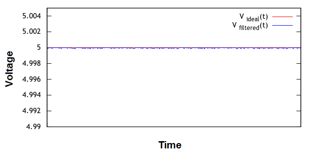
As a result, the smoothed voltage looks like this:
The typical capacitor used for this purpose is ceramic, rated at 10 or 100 nF. Large electrolytic capacitors are poorly suited for this role because they are slower and will not be able to give up their charge quickly in these environments where noise has a high frequency.
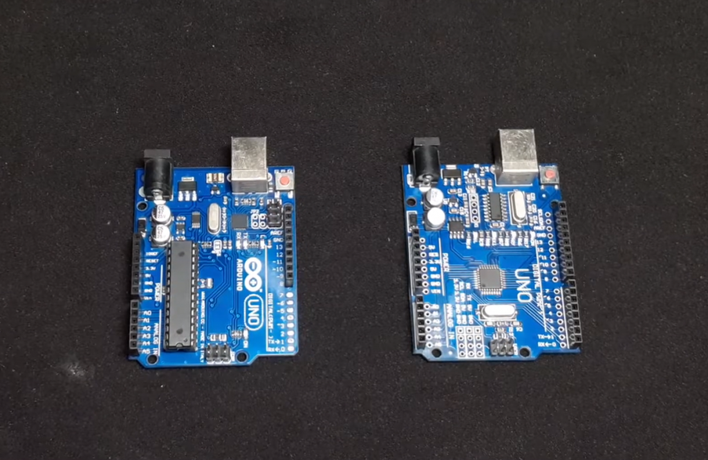
In one device, bypass capacitors can be present in many places: in front of each circuit, which is an independent unit. For example, the Arduino already has bypass capacitors that ensure stable operation of the processor, but before powering the LCD screen connected to it, it must have its own.
Filter Capacitor
A filter capacitor is used to remove a signal from a sensor that transmits it in the form of a varying voltage. Examples of such sensors are a microphone or an active Wi-Fi antenna.
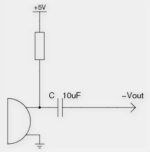
Consider the wiring diagram of an electret microphone. The electret microphone is the most common and ubiquitous: it is the one used in cell phones, computer accessories, hands-free systems.
The microphone requires power to work. In the state of silence, its resistance is high and amounts to tens of kilohms. When it is affected by sound, the gate built inside a field-effect transistor opens, and the microphone loses internal resistance. The loss and recovery of resistance occur many times every second and corresponds to the sound wave phase.
We are only interested in the voltage at the output when there is sound. If there were no capacitor C, the output would always be additionally influenced by the DC voltage. C blocks this DC component and only lets in deflections that correspond to the sound.
The audible sound that we are interested in is in the low-frequency range: 20 Hz – 20 kHz. In order to isolate from the voltage exactly the sound signal and not the high-frequency noise of the power supply, a slow 10 µF electrolytic capacitor is used as C. If a fast capacitor were used, such as a 10 nF capacitor, signals unrelated to the sound would pass through to the output.
Note that the output signal is supplied as a negative voltage. That is, when you connect the output to the ground, the current will flow from the ground to the output. The peak voltages in the case of a microphone are in the tens of millivolts. The Vout output is usually connected to an operational amplifier to reverse the voltage and increase its value.
Connecting Capacitors
If you compare with the connection of resistors, the calculation of the final rating of capacitors looks the other way around.
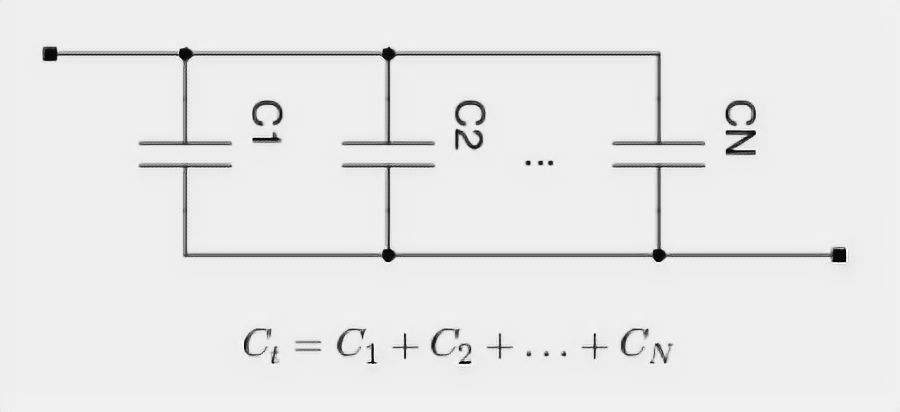
When connected in parallel, the total capacitance is summed up:
When connected in series, the total capacitance is calculated using the formula:
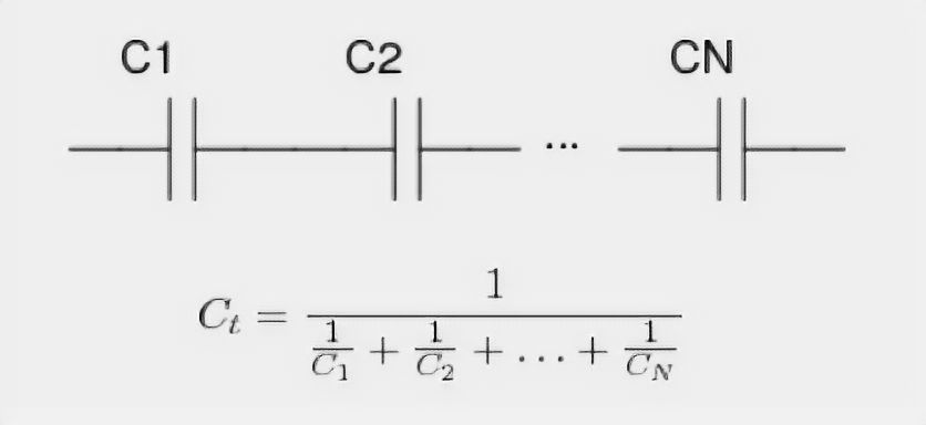
If there are only two capacitors, then in series connection:

In the special case of two identical capacitors, the total capacitance of the series connection is equal to half the capacitance of each.
Maximum characteristics
The documentation for each capacitor indicates the maximum permissible voltage. Exceeding it can lead to dielectric breakdown and capacitor explosion. For electrolytic capacitors, the polarity must always be observed. Otherwise, either the electrolyte will leak out or, again, there will be an explosion.
FAQ
Which tools can I use to test electrolytic and ceramic capacitors?
A multimeter is a tool that measures the voltage, current, capacitance, resistance, or power in one or more circuits. A capacitor tester is a tool that can be used to test capacitors for defects like cracks and leaks by measuring the capacitance of a capacitor when it is charged with an electric charge.
Are Fluke multimeters good for testing electrolytic and ceramic capacitors?
Fluke multimeters are good tools for testing capacitors and other electrical components. They can measure voltage, current, resistance, and more. However, there are some limitations to using them for ceramic capacitors. For example, Fluke cannot measure the temperature of a ceramic capacitor with a Fluke multimeter because it is not designed to measure temperature.
Are budget multimeters good for testing electrolytic and ceramic capacitors?
Yes, budget multimeters are good for testing electrolytic and ceramic capacitors. They are able to measure capacitance, which is the most important factor in determining the quality of a capacitor.
Are electrolytic capacitors better than ceramic?
Electrolytic capacitors are good for low-frequency applications, while ceramic capacitors are best for high-frequency and large-value applications. Ceramic capacitors have a lower ESR and higher ripple current than electrolytic ones.
Final Words
In this article, we explained the difference between electrolytic and ceramic capacitors. The article gave you a basic understanding of these two types of capacitors and their applications in electronics circuit design. Thanks for reading!


I have always been a bit of a techie, so when it came time to start working on my first electronics project, I did a lot of research on capacitors. I quickly learned about the difference between electrolytic and ceramic capacitors, and I decided to go with electrolytics because they can store more energy.
I was a bit worried that I might have made the wrong choice, but it turns out that electrolytic capacitors are perfectly suited for this project. They worked flawlessly, and they provided the stability and power that I needed.
Ceramic capacitors are definitely good for certain applications, but for my project, electrolytic capacitors were the right choice.