
It is very useful for beginner radio amateurs to know how to check the transformer with a multimeter. Such knowledge is useful for the reason that it saves time and money. In most linear power supplies, the transformer is the lion’s share of the cost. Therefore, if you have a transformer with unknown parameters in your hands, do not rush to throw it away. It is better to take a multimeter in your hands. For some experiments, we also need an incandescent bulb with a bullet.
To perform further experiments and experiments more consciously, you should understand how the transformer is arranged and operates. Let’s consider it here in a simplified form.
The simplest transformer is two windings wound on a core or a magnetic circuit. Each winding is a conductor insulated from the other. The core is made of thin insulated sheets of special electrical steel. One of the windings, called the primary winding, is energized, and the other, called the secondary winding, is removed.
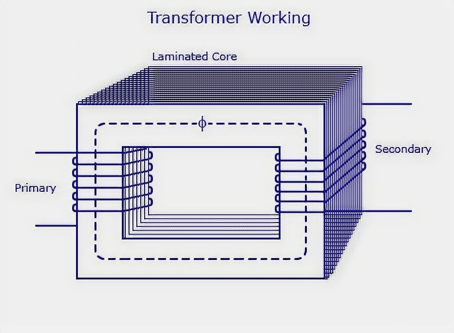
When an alternating voltage is applied to the primary winding, a bullet is created in the primary winding for the flow of alternating current because the electrical circuit is closed. An alternating magnetic field is always formed around a conductor with alternating current. The magnetic field is short-circuited and amplified by the core of the magnetic wire and leads an alternating electromotive force of the EMF in the secondary winding. When the load is connected to the secondary winding, an alternating current of i2 flows in it.
This knowledge is not yet enough to fully understand how to test a transformer with a multimeter. Therefore, let us consider some more useful points.
How to Test a Transformer with a Multimeter Correctly
Without going into details, which are not necessary here, we note that the EMF and the voltage are determined by the number of windings with other equal parameters
E ~ w.
The more windings, the higher the value of EMF (or winding voltage). In most cases, we are dealing with step-down transformers. Their primary winding is supplied with a high voltage of 220 V (230 V in the new State Standard), and the secondary winding is removed from the low voltage: 9 V, 12 V, 24 V, etc. Accordingly, the number of windings will also be different. In the first case, it is higher, and in the second case, it is lower.
As far as
E1 > E2,
then
w1 > w2.
Also, without giving any reasoning, we should note that the power of both windings is always equal:
S1 = S2.
And since the power is a product of current i at voltage u
S = u∙i,
then
S1 = u1∙i1; S2 = u2∙i2.
From where we get a simple equation:
u1∙i1 = u2∙i2.
The latter expression has a great practical interest for us, which is as follows. To maintain the balance of primary and secondary winding capacities, we need to reduce the current as of the voltage increases. Therefore, a smaller current flows in a high-voltage winding and vice versa. Simply put, since the voltage in the primary winding is higher than in the secondary one, the current in it is less than in the second one. In this case, the proportion is preserved. For example, if the voltage is ten times higher, the current is ten times lower than in the second one.
The ratio of the number of windings or ratio of the primary to the secondary EMF is called the ratio of transformation:
kt = w1 / w2 = E1 / E2.
From the above, we can draw the most important conclusion, which will help us understand how to check the transformer multimeter.
The conclusion is as follows. Since the transformer’s primary winding is designed for a higher voltage (220 V, 230 V) than the secondary (12 V, 24 V, etc.), it is wound with a large number of windings. But it has a smaller current flow, so it uses a thinner wire of a longer length. It follows from this that the primary winding of the step-down transformer has a higher resistance than the secondary one.
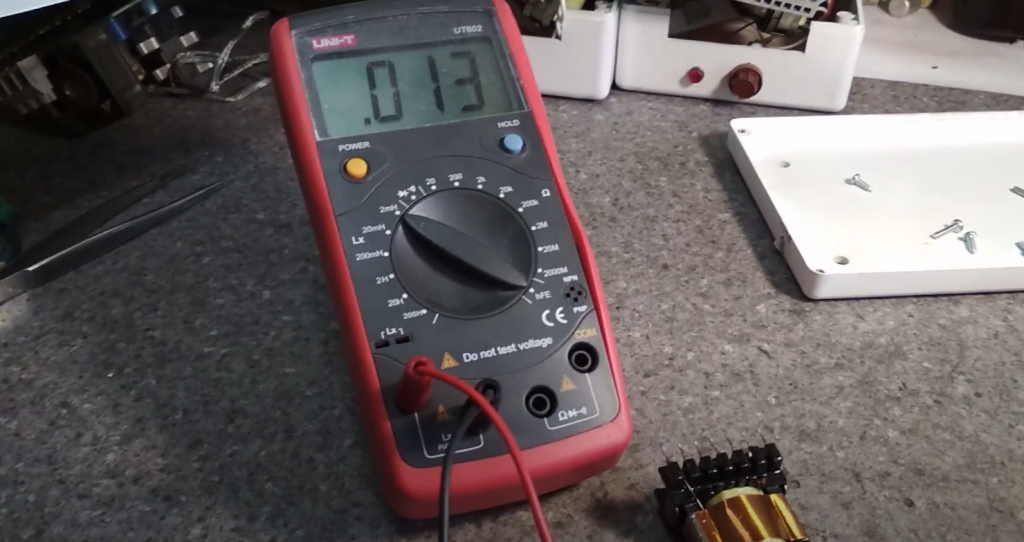
Therefore, with the help of a multimeter, it is already possible to determine which leads are the primary and secondary leads by measuring and comparing their resistances.
How to Identify the Transformer Windings
After measuring the resistance of the windings, we learned how they are designed for higher voltages. But we do not yet know if it can be fed with 220 V. After all, a higher voltage still means 220 V. Sometimes, you get transformers that are designed for 110 V and 127 V AC or less. Therefore, if such a transformer is included in the 220 V network, it will simply burn.
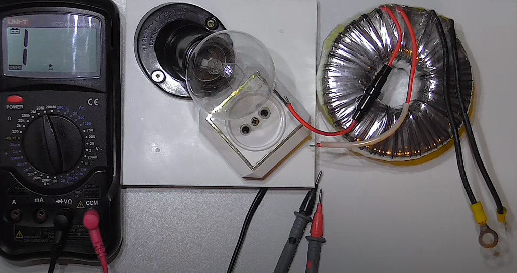
In this case, experienced electricians do so. They take an incandescent lamp and connect it to the expected primary winding in series. Then one winding output and the output of the lamp is connected to the 220 V network. If the transformer is designed for 220 V, the lamp will not light up because the applied voltage of 220 V is fully balanced with the self-induction EMF of the winding. EMF and applied voltage are directed oppositely. Therefore, a small current – transformer idle current – will flow through the incandescent lamp. The value of this current is not sufficient to heat up the filament in the incandescent lamp. For this reason, the lamp is not glowing.
If the lamp illuminates even at full intensity, such a transformer can not be supplied with 220 V; it is not designed for such voltage.
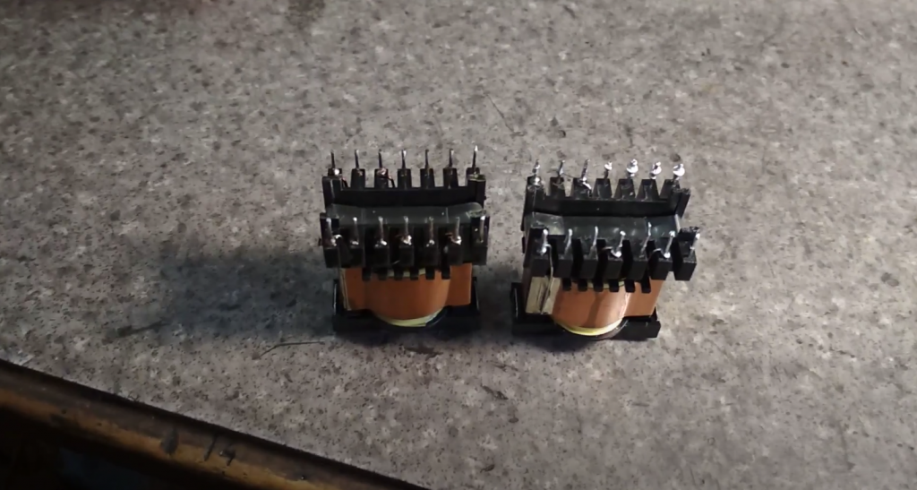
Very often, you can find a transformer with many leads. This means that it has several secondary windings. You can recognize the voltage of each of them as follows.
Previously, we looked at how to check a transformer with a multimeter and determine the primary winding with respect to resistance. You can also use an incandescent lamp to make sure that it is designed for 220 V (230 V).
Now it is a small matter. Supply to the primary winding 220 V and measure the AC voltage on the remaining windings’ outputs with a multimeter.
Connecting the Transformer Windings
The secondary windings of the transformer are connected in series and less often in parallel. In the case of a serial connection, the windings can be switched on in and out of sequence.
The matching of the transformer windings is used to obtain a higher voltage than one of the windings. In the case of a consensual connection, the beginning of one winding, indicated by a dot or cross in the wiring diagrams, is connected to the end of the previous winding. Here, remember that the maximum current of all connected windings should not exceed the value of the one calculated for the smallest current.
At a counter connection, the beginning or ends of the windings are connected together. In case of a cross-connection, the EMFs are directed counter-current. At the outputs, the EMFs’ difference is obtained: the smaller value is taken from, the larger one. If two windings with equal values of EMU are connected on the counter connection, there will be zero at the outputs.
Now you know how to test the transformer with a multimeter, and you can also find the primary and secondary windings.


