

Fritzing is a very popular environment for creating prototypes of projects, schemes, and illustrations. It is often used in projects, including those based on Arduino, Raspberry Pi, and other platforms. Fritzing is easy to download and configure and has a simple and intuitive interface. Enthusiasts from all over the world create component and module libraries for a wide variety of device classes. In this article, we will consider the first steps to download, install, and configure Fritzing and work with Arduino projects.
Download Fritzing
The Fritzing program was developed at the University of Applied Sciences in Potsdam in 2009. There are currently versions for Windows, Mac OS (10.4 and higher), and Linux (2.6 and higher). The development environment has been translated into English, Russian, Japanese, Chinese and other languages. Fritzing has a simple and intuitive interface.
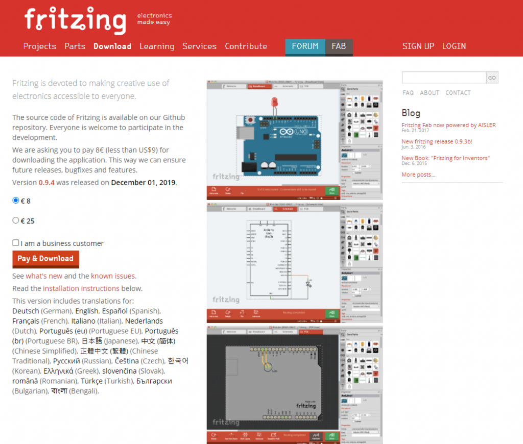
Fritzing can be downloaded absolutely free from the official website. The latest versions of the distributions are presented there, though they differ slightly from previous editions. The process is quite simple – the user selects the right operating system and downloads Fritzing. The installation process is not complicated; you need to follow the instructions of the installer on display.
Setting Up the Program
After opening the program, you can see three modes:
- breadboard;
- circuit diagram;
- printed circuit board.
Layout mode is used to create a virtual project. It will look the same as the real scheme of the device. The circuit diagram does not show the real image but close to the traditional one, which is used by engineers. It is built automatically after you create it in breadboard mode. You can design and export the necessary data to obtain the printed circuit board in the latter mode.
The First Steps
Algorithm of work in the program:
- Creation of the real scheme and analysis of its performance;
- transfer of the scheme to the Fritzing program, its editing;
- setting the necessary characteristics to the elements which make up the scheme;
- switching the operation mode, each of which can be used as the main working environment;
- PCB design – you can view the layout;
- documenting.
After project creation in the Fritzing environment, you may implement it in real conditions.
Fritzing has its own libraries, which help to simplify the work. After downloading, there are a number of installed libraries with standard components. There are libraries for various modules, shields, sensors, integrated circuits, and microcontroller boards. They can be downloaded and installed. You can add a new element to the library. To do this, go to the menu Mine – My parts, right-click on “import,” and select the desired file with format .fzpz, .fbz, or .fzbz. After that, it will appear in the library. Then, you need to click on Mine and select Save Bin to save the program’s component after you finish.
Starting Work at Fritzing
When you open the program for the first time, the Welcome window will appear.
There are modes of operation in the upper part of the window. If you click on “Layout board,” the following window will appear:
Before you start building the layout, you need to adjust the environment according to the user’s needs. To do this, go to Windows and select those windows, which will be placed in the environment. The selected windows are dragged to any place in the workspace.
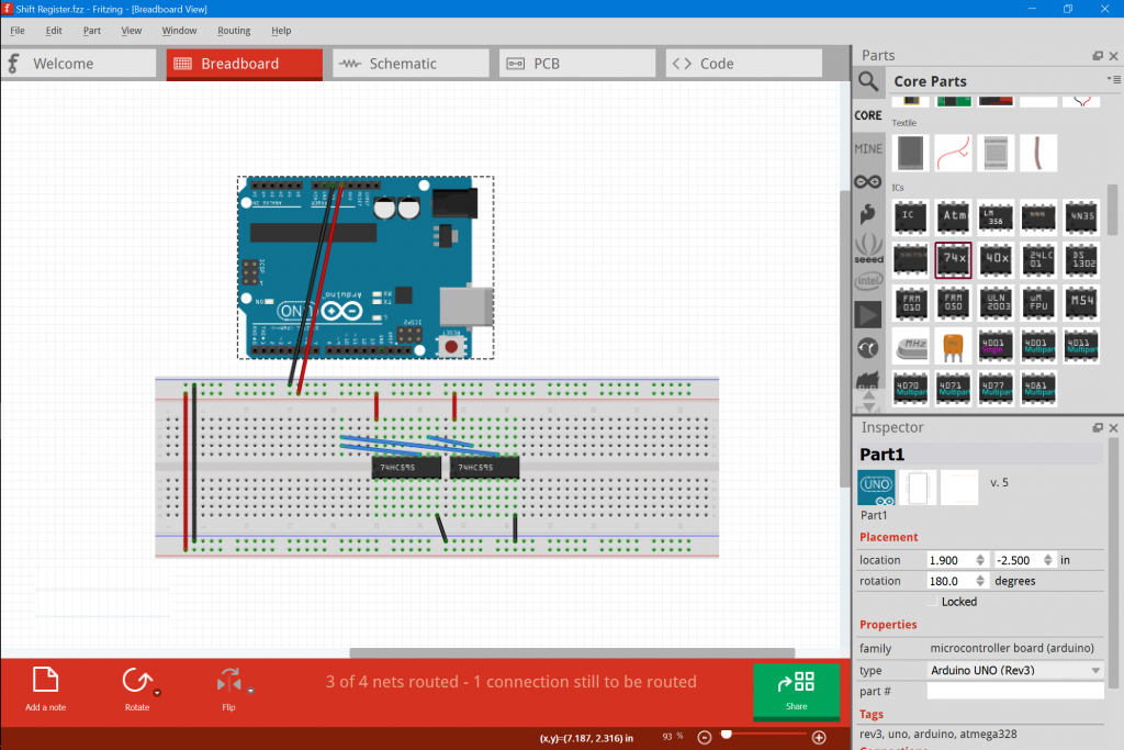
Then you can start schema creation in the program. There is a toolbar on the right side of the screen that stores all installed electronic components, boards, and sensors. Under them, there is a menu where you can adjust the parameters (resistor resistance, capacitor capacity).
To create your own project, you need to draw a diagram. The necessary component is selected from the Basic Library and dragged to the working part so that its outputs match the columns on the layout board. For example, you may connect a resistor:
If the resistor is set correctly, the columns will light up green. Then you need to set the necessary device characteristics. This is done in the lower right part of the “Inspector” foam. After setting the required resistance, it’s correct marking with colored rings will be graphically shown. A specified angle can rotate the component – to do this, click the right mouse button on the “rotate” and select the desired angle. This parameter is also set in the rotate in the side menu.
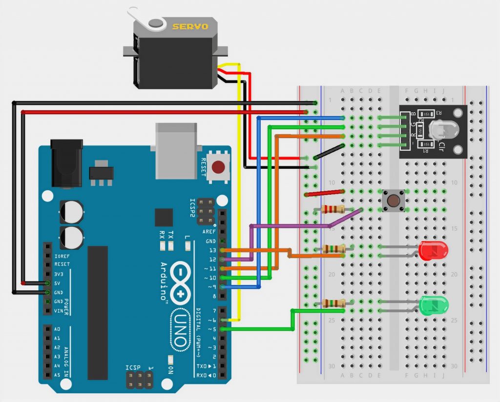
It is possible to place another component on the board. To create the simplest LED power supply scheme, you need only a resistor and the light-emitting diode itself. It is also selected from a set of elements and mounted on the circuit on non-contact green lines.
Then you need to connect the LED and the resistor with wires. To do this, the cursor is pointing at an opening on the board. It should turn blue, which means that you can bring the wire to the desired point. You need to click the left button on the hole, and with the button pressed, bring the conductor to the desired point.
A battery will power it. It is located in the Power library and is installed on the model board. Connect the elements, as shown in the figure below.
On the “Circuit diagram” tab, you should edit the received connections to a tidy appearance by dragging and dropping the elements to achieve an optimal and clear scheme. You can do this by clicking on the button in the lower-left corner of the Autotracing tab.
To use the scheme further, you should save it. To do it, go to “File” -> “Export” -> As image, select the necessary format and name, and save the document.
You may create a new element or upgrade an existing one by yourself in the program. The second way is more straightforward. To do this, select a suitable element from the library and drag it to the workspace. Then the component editor is launched to click on the component and select Edit (new parts editor). A tab with Breadboard editing will appear. There will also appear other tabs where you will set the necessary parameters for the new element. There are only six main editing sections: layout, circuit diagram, circuit board, icon, metadata, connections.
To create an object from scratch, the whole complex will be in the diagram of the component. The vector graphics are edited in an external editor that supports the SVG format. You can find basic component templates on the Internet, edit them in any program, and upload them to Fritzing.


