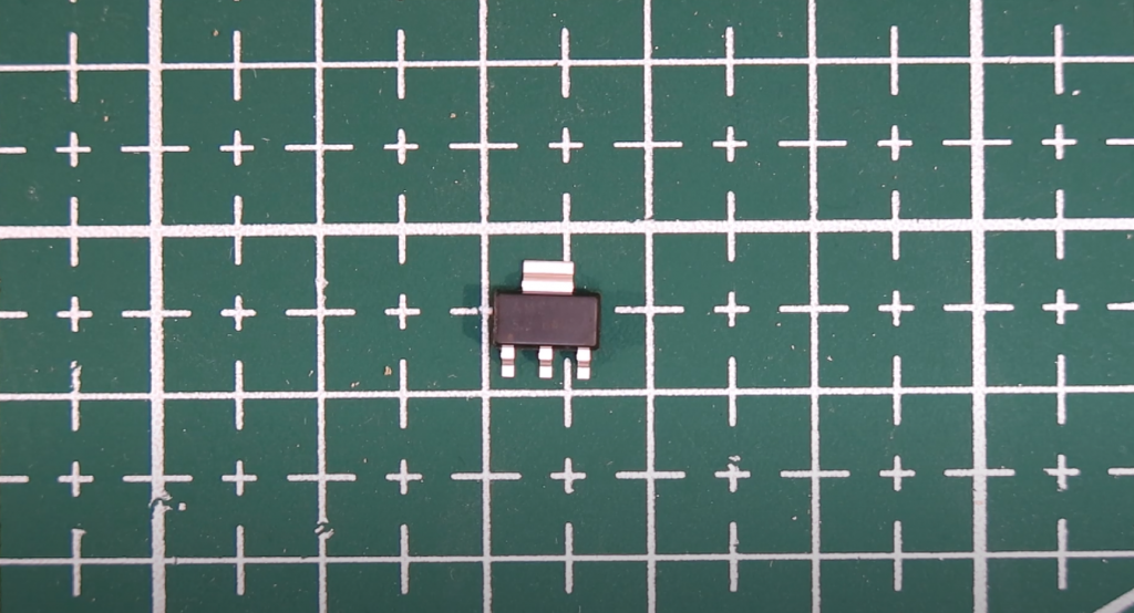
In case the circuit needs a regulator for some non-standard voltage, then an excellent solution is to use the popular LM317T integrated regulator with characteristics:
- capable of operating in a range of output voltages from 1.2 to 37 V;
- the output current can reach 1.5 A;
- the maximum power dissipation is 20 W;
- built-in current limitation, for short-circuit protection;
- built-in overheat protection.
LM317T Pinout
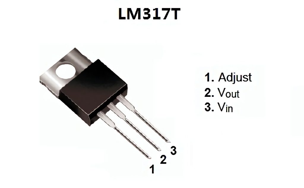
| Pin Number | Pin Name | Description |
| 1 | Adjust | This pin adjusts the output voltage |
| 2 | Output Voltage (Vout) | The regulated output voltage set by the adjusted pin can be obtained from this pin |
| 3 | Input Voltage (Vin) | The input voltage which has to be regulated is given to this pin |
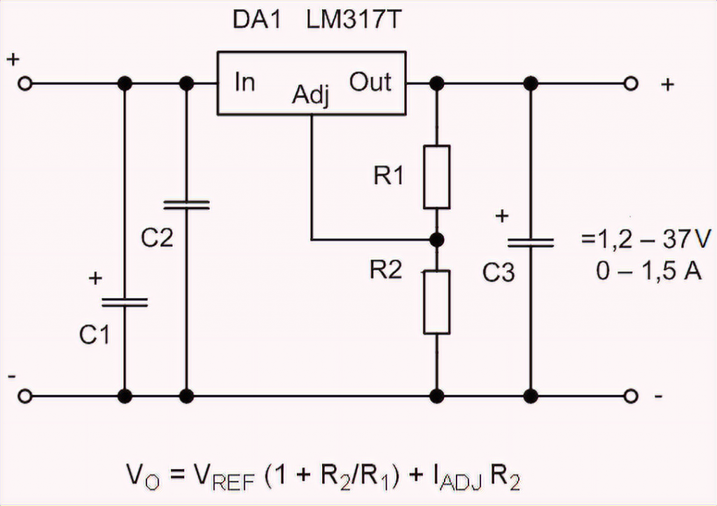
The LM317T circuit in the minimum version has two resistors, the resistance values determining the output voltage, the input and output capacitors.
The regulator has two important parameters: the reference voltage (Vref) and the current flowing from the tuning pin (Iadj).
The value of the reference voltage can vary from instance to instance from 1.2 to 1.3 V, but the average is 1.25 V. The reference voltage is the voltage that the regulator chip tends to maintain at the resistor R1. So if resistor R2 is closed, the circuit’s output will be 1.25V, and the greater the voltage drop across R2, the greater will be the output voltage. It turns out that the 1.25V at R1 is added to the voltage drop at R2 to form the output voltage.
The second parameter, the current flowing from the trim output, is essentially parasitic. The manufacturers promise that it will average 50 µA, max 100 µA, but in real life, it can reach 500 µA. Therefore, to ensure a stable output voltage, you have to drive a current of 5mA and more through the R1-R2 divider. And this means that R1 resistance can not exceed 240 Ohm. By the way, this is the recommended resistance in the circuit diagrams from the datasheet.
Example of Voltage Stabilization Using an LM317
Suppose you want to supply 12 volts to the chip and adjust it to 5 volts. From the formula above, for the LM317 to output 5 volts and act as a voltage regulator, the R2 value must be 720 ohms.
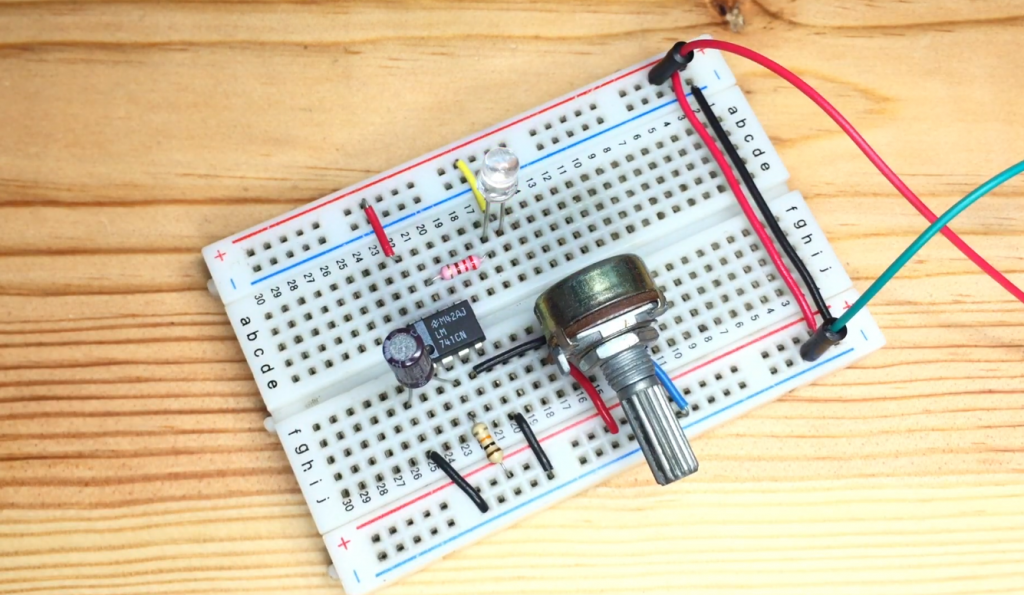
Assemble the above circuit. Then use a multimeter to check the output voltage by placing the probe on a 1 uF capacitor. If the circuit is assembled correctly, the output will be about 5 volts.
The input capacitor C1 can be omitted if the chip housing is at least 15 centimeters from the input smoothing filter. The output capacitor C2 is added to smooth the transients.
Now replace resistor R2 and replace it with a 1.5 kOhm resistor. The output should now be about 10 V. This is an advantage of these microcircuits. You can adjust them to any voltage within the range specified in its specifications.
The first time I calculated the divider for an IC using the formula from the LM317T datasheet, I set the current to 1 mA, and then I wondered for a long time why the voltage is different. And since then, I set R1 and calculate by the formula:
R2=R1*((Uout/Un)-1)
I test in real conditions and specify the resistance values of R1 and R2.
Let’s see what should be for widespread voltages of 5 and 12 V.
| R1, Ohm | R2, Ohm | |
| LM317T circuit diagram 5v | 120 | 360 |
| LM317T circuit diagram 12v | 240 | 2000 |
But I would advise using LM317T for typical voltages only when you need to do something on the spot, and you don’t have a suitable chip like 7805 or 7812 handy.
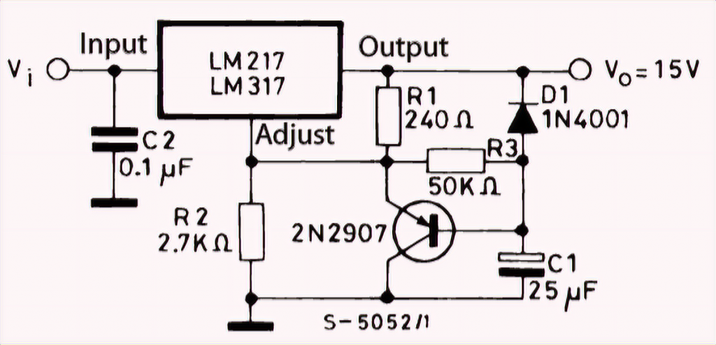
The LM317T can also be used to make a soft-start circuit: add a capacitor and a current amplifier on a bipolar PNP transistor.
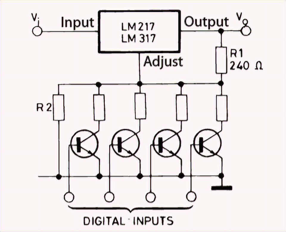
The switching circuit for digital control of the output voltage is not complicated either. Calculate R2 to the maximum voltage required and add a chain of resistor and transistor in parallel. The transistor’s inclusion will add in parallel to the conductivity of the main resistor, the conductivity of the additional resistor. And the output voltage will decrease.
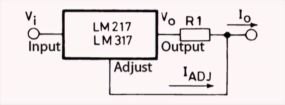
A current regulator circuit is even simpler than a voltage regulator because only one resistor is needed. I out = Uon/R1.
For example, in this way, we get a current regulator for LEDs from lm317t:
- for single watt LEDs I = 350 mA, R1 = 3.6 ohms, at least 0.5 W.
- for three-watt LEDs I = 1 A, R1 = 1,2 Ohm, power not less than 1,2 W.
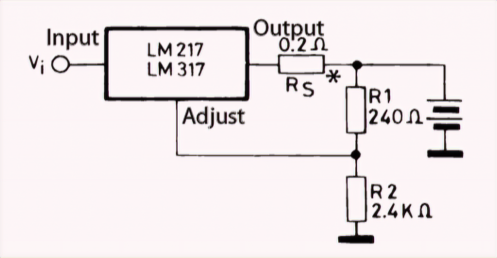
It is easy to make a 12V battery charger based on the AVR. This is what the datasheet suggests. With Rs, you can set the current limitation, and R1 and R2 determine the voltage limitation.
If the circuit needs to stabilize voltages at currents greater than 1.5A, you can still use the LM317T, but together with a powerful bipolar transistor or PNP structure.
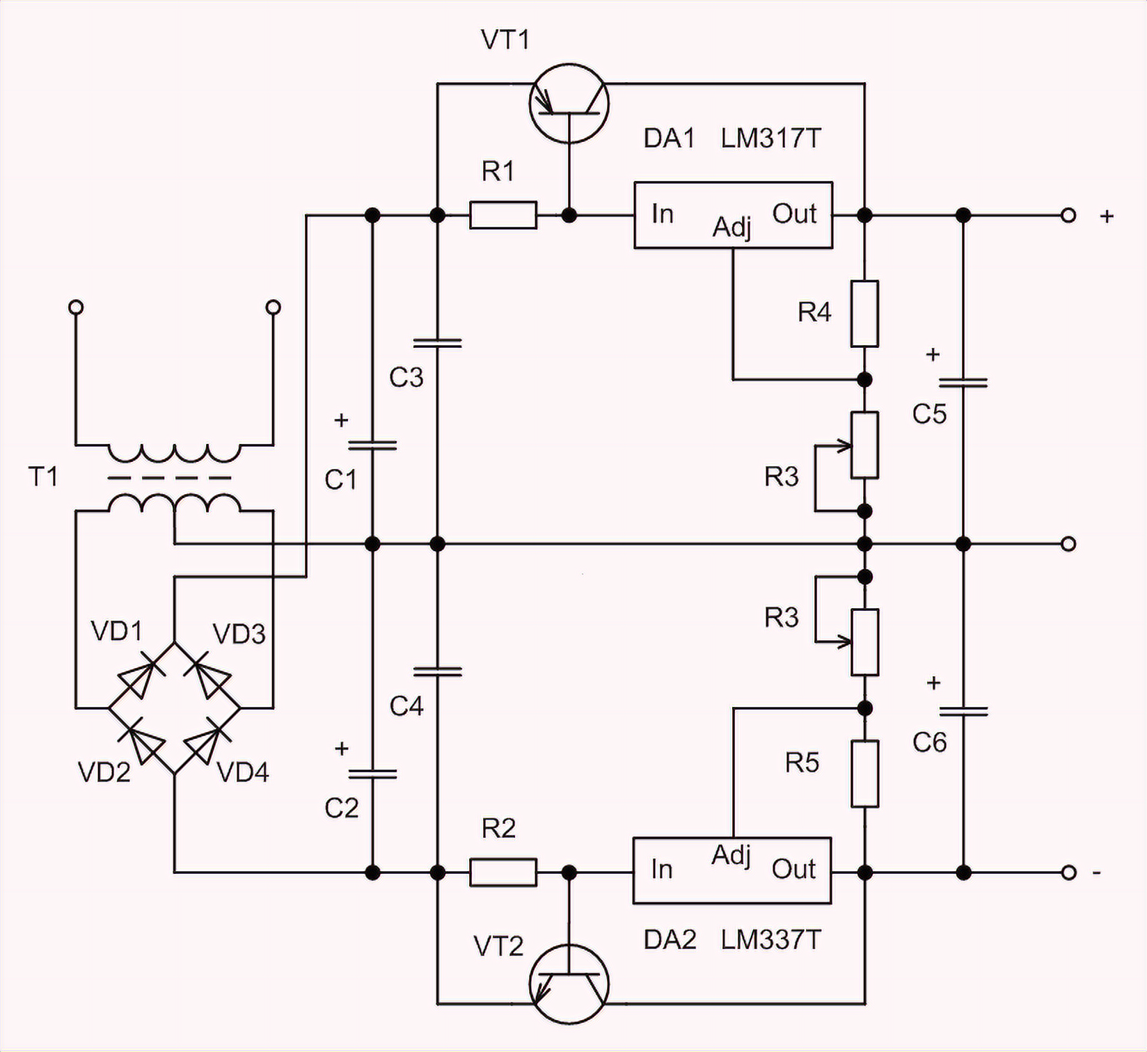
If you need to build a bipolar regulated voltage regulator, the LM317T analog will help, but it works on the regulator’s negative side – the LM337T.
But this chip has some limitations. It is not a low-voltage-drop regulator. Even the opposite starts to work well only when the difference between the output voltage and output voltage exceeds 7V.
If the current does not exceed 100mA, it is better to use the LP2950 and LP2951 low-drop chips.
How to check the LM317T with a multimeter?
It is not possible to check microcircuits with a multimeter because it is not a transistor. Something can be tested between the pins, of course, but this does not guarantee the chip’s serviceability, as it contains a large number of different radio elements (transistors, resistors, etc.) which are not connected to the pins directly and do not “test”. The most effective way is to assemble a simple test bench using a breadboard to test and power everything from a battery. The test bench should be a simple stabilizer (a couple of capacitors and resistors).
Powerful LM317T Alternatives – LM350 and LM338
If a 1.5A output current is not enough, you can use:
- LM350AT, LM350T – 3 A and 25 W (TO-220 package)
- LM350K – 3 A and 30 W (package TO-3)
- LM338T, LM338K – 5 A
The manufacturers of these regulators promise a reduced current regulating input to 50µA and improved accuracy of the reference voltage. The circuit diagrams are suitable for the LM317.