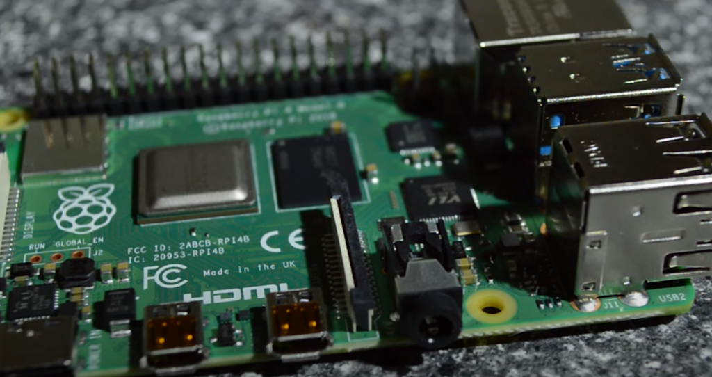
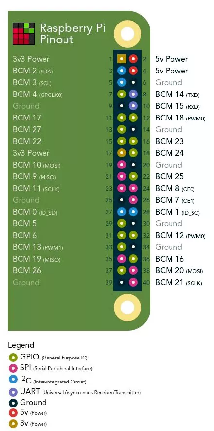
Let’s take a closer look at the pinout of the new Raspberry Pi 4 GPIO board and examine each function in detail.
GPIO
GPIO, or general-purpose input/output interface, is an interface for communication between components in a computer system, such as a microprocessor and various peripherals. GPIO pins can act both as input and output – this is usually configurable. GPIO pins are often grouped into ports.
In many ways, the Raspberry Pi 4 improves the capabilities of earlier Pi models. Not only does the single-board computer support more RAM, faster processor speeds, and advanced peripherals, but the GPIO pins retain their standard features set by previous models, along with additional features for existing pins. Let’s take a look at what the standard 40 pins on the Raspberry Pi do, and then take a closer look at each of these features.
As I wrote earlier, the GPIO is the General Purpose Input/Output Interface.
A general-purpose I/O interface is what GPIO stands for and perfectly describes how the Raspberry Pi boards pins work. They are very similar to Arduino pin ports in that they can be configured to read inputs or write outputs. These pins allow your Pi to communicate with various components such as buttons, potentiometers, and buzzer.
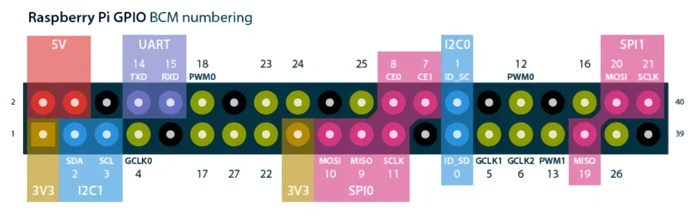
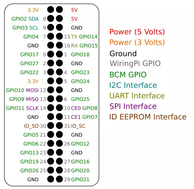
There are two naming schemes you should be familiar with: WiringPi numbering and Broadcom numbering. The latter is what each pin is officially called, shown in green in the image above. WiringPi, the GPIO interface library that you will most likely use. It has its own hardware-independent numbering system. Remember to check which pin you are actually working with when programming the Pi.
Power and Ground Pins
The power and ground pins are used for external power circuits. All Raspberry Pi with standard 40 GPIO pins will have two 5V pins and two 3.3V pins, always in the same location.
Along with the 5V and 3.3V pins, eight ground (GND) pins are available. The power and ground contacts allow you to power your Raspberry Pi components, such as LEDs and motors. Remember, however, that you should always install the proper components or external circuitry before powering anything through these pins. Powering anything with too much current or significant voltage spikes, such as a motor without a proper motor controller, will damage the pins and may make them unusable.
Alternate Functions
While many projects can get along with power and input pins, sometimes the Pi is required to have different abilities. Fortunately, some GPIO pins double as I2C, SPI, and UART interfaces. The Pi 4 has expanded the capabilities of many of the pins, supporting these interfaces on more of them than the Raspberry Pi 3b+ and before it. Below is a brief description of each interface.
I2C
I2C, or Inter-Integrated Circuit protocol, allows your Raspberry Pi to control multiple sensors and components, known as slaves. Communication is through SDA (data output) and SCL (clock output). Each slave device is created with a unique address to allow fast communication with many devices. The ID_EEPROM pins are also I2C but are used to communicate with additional boards rather than slave components.
SPI
SPI, or Serial Peripheral Interface, is also used to control components with master-slave (master-slave) relationships, although it is not as compact. It requires a clock (SCLK), Master Out Slave In (MOSI) pins, and Master In Slave Out pins. The pins do what their names imply, with SCLK controlling the data rate, MOSI is used to send instructions from the Pi to connected devices, and MISO does the opposite.
UART
If you’ve worked with Arduino before, you may have heard of UART or Serial (serial communication). A universal asynchronous receiver/transmitter is used to connect Arduino boards to the computers that program them and communicate between other devices with receive and transmit pins. These pins can be used to control your Pi via another computer if the serial console is enabled in raspi-config or to directly control the Arduino if you can’t use a USB cable for your project.
PWM
Among other functions, all pins support software PWM, and GPIO12, GPIO13, GPIO18, GPIO19 support hardware pulse width modulation.
Raspberry Pi Official 40-pin List
Although the standard pinout for all 40-pin Raspberry Pi devices remains the same, you can find an updated feature list for the Raspberry Pi 4 in the official raspi-gpio repository on GitHub.
If you keep forgetting which pin does what? Below you can print out a pinout of the Raspberry Pi B+ created by Andreas Gore (better known as Splitbrain).
His design can be printed out and placed right on top of the board to make it easier to remember all the pins.