
Interrupts are a fundamental Arduino mechanism that allows external devices to communicate with the controller when different events occur. By setting a hardware interrupt handler in the sketch, we can respond to the button turning on or off, the keyboard press, the mouse press, the RTC timer ticks, the reception of new data via UART, I2C, or SPI. This article will learn how to interrupt work on Arduino Uno, Mega, or Nano boards and give an example of how to use the Arduino attachInterrupt() function.
Interrupts in Arduino
An interrupt is a signal that tells the processor that an event has occurred and needs immediate attention. The processor has to react to this signal by interrupting the execution of the current instructions and passing the control to the Interrupt Service Routine (ISR) handler. The handler is a function we write ourselves and put there the code which should respond to the event.
After handling an ISR interrupt, the function finishes its work, and the processor happily returns to the interrupted activity – it continues to execute the code from where it left off. All this happens automatically, so our task is to write an interrupt handler without breaking anything without making the processor too often distracted by us. We need to understand the circuitry, the principles of the connected devices, and how often an interrupt can be triggered, the peculiarities of its occurrence. All this is the main difficulty of working with interrupts.
Hardware and Software Interrupts
Interrupts in Arduino can be of several kinds:
- Hardware interrupts. Interrupts at the microprocessor architecture level. The event itself can occur at a productive moment from an external device – for example, pressing a button on the keyboard, moving a computer mouse, etc.
- Software interrupts. Are triggered within a program by special instruction. They are used to trigger an interrupt handler.
- Internal (synchronous) interrupts. Internal interrupts occur due to a change or disturbance in program execution (e.g., invalid address, invalid operation code, and others).
Why Do We Need Hardware Interrupts?
Hardware interrupts occur in response to an external event and come from an external hardware device. The Arduino provides four types of hardware interruptions. They all differ in the signal on the interrupt pin:
- The pin is pulled to the ground. The interrupt handler is executed as long as there is a LOW signal on the interrupt pin.
- Changing the signal on the pin. The Arduino then executes an interrupt handler when there is a signal change on the interrupt pin.
- Changing the signal from LOW to HIGH on the pin – an interrupt handler will be executed when the signal changes from low to high.
- Changing the signal from HIGH to LOW on the pin – when changing from a high signal to a low one, the interrupt handler will be executed.
Interrupts are helpful in Arduino programs because they help solve timing problems. For example, with UART interrupts, you don’t have to keep track of every character coming in. An external hardware device signals an interrupt. The processor immediately calls an interrupt handler, which captures the symbol in time. This saves CPU time that, without interrupts, would be spent checking the status of the UART. Instead, all necessary actions are performed by the interrupt handler without affecting the main program. No special features are required from the hardware device.
The main reasons why an interrupt needs to be called are:
- Determination of a change in output state;
- Timer interrupts;
- SPI, I2C, USART data interrupts;
- Analog to digital conversion;
- Readiness to use EEPROM, flash memory.
How Interrupts are Handled in the Arduino
When an interrupt signal is received, work in the loop() is paused. The execution of the function that is declared for execution at the interrupt signal starts. The declared function cannot accept input values and cannot return values when it terminates. The code itself is not affected by an interrupt in the main program loop. The standard attachInterrupt() function is used to handle interrupts in Arduino.
Differences in the Implementation of Interrupts in Different Arduino Boards
Depending on the hardware implementation of a particular microcontroller model, there are several interrupts. The Arduino Uno board has two interrupts on the second and third pins, but if more than two outputs are required, the board supports a special “pin-change” mode. This mode works by changing the input for all pins. The input change interrupts mode because interrupts can be generated on any of the eight pins. Processing, in this case, will be more complicated and longer because you will have to keep track of the last state on each of the pins.
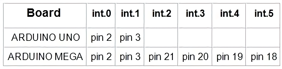
On other boards, the number of interrupts is higher. For example, the Arduino Mega 2560 board has six pins that can handle external interrupts. For all Arduino boards, when working with attachInterrupt(interrupt, function, mode), the argument Interrupt 0 is connected to digital pin 2.
Interrupts in the Arduino Language
Now let’s get practical and talk about how to use interrupts in your projects.
The Syntax of attachInterrupt()
The attachInterrupt function is used to handle interrupts. It connects an external interrupt to the interrupt handler.
Call syntax: attachInterrupt(interrupt, function, mode)
Function arguments:
- interrupt – the number of the interrupt to be called (0 is standard for pin 2, for the Arduino Uno board 1 is for pin 3);
- function – the name of the function to call at interrupt (important – the function must neither accept nor return any values);
- mode – interrupt triggering condition.
You can set the following options for interrupt conditions:
- LOW – executed on the low signal level when there is zero value on the contact. The interrupt can be cyclically repeated – for example, when the button is pressed.
- CHANGE – on edge, interrupt occurs when the signal changes from high to low or vice versa. It is executed once at any signal change.
- RISING – Executes an interrupt once when the signal changes from LOW to HIGH.
- FALLING – Executes an interrupt once when the signal changes from HIGH to LOW.4
Important Notes
When working with interrupts, you must always consider the following significant limitations:
- The interrupt handler function must not take too long to execute. This is because the Arduino cannot handle several interrupts at the same time. While your handler function is running, all other interrupts will be ignored, and you will miss important events. If you need to do something big, just pass the event handler in the main loop(). You can only set the event flag in the handler, and in the loop, you can check the flag and handle it.
- You have to be very careful with variables. The intelligent C++ compiler can “re-optimize” your program by removing variables it deems unnecessary. The compiler will not see that you set some variables in one part and use them in another. To avoid this possibility in the case of basic data types, you can use the keyword volatile, for example, volatile boolean state = 0. But this method will not work with complex data structures. So you have to be always on your guard.
- It is not recommended to use a large number of interrupts (try not to use more than 6-8). A large number of different events require a serious complication of the code and thus leads to errors. Furthermore, it must be understood that no temporal precision of execution in systems with many interrupts is out of the question – you never know the interval between the calls of the important for your commands.
- It is categorically forbidden to use
delay()in handlers. The mechanism for determining the delay interval uses timers, and they also work on interrupts, which will block your handler. As a result, everyone will be waiting for everyone else, and the program will hang. For the same reason, you should not use interrupt-based communication protocols (e.g., I2C).
Examples of Using attachInterrupts()
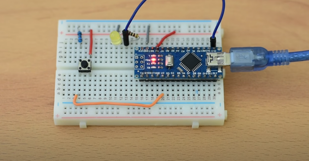
Let’s get practical and take a look at a simple example of how to use interrupts. In this example, we define a handler function that, when the signal on pin 2 of the Arduino Uno changes, switches the state of pin 13, to which we traditionally connect the LED.
#define PIN_LED 13

volatile boolean actionState = LOW;
void setup() {
pinMode(PIN_LED, OUTPUT);
// set an interrupt
// the myEventListener function is called when
// on pin 2 (interrupt 0 is tied to pin 2)
// the signal changes (no matter in what direction)
attachInterrupt(0, myEventListener, CHANGE);
}

void loop() {
// We don't do anything in the loop function since all of the event handling code will be in the myEventListener function
}

void myEventListener() {
actionState != actionState; //
// Perform other actions, e.g. turn the LED on or off
digitalWrite(PIN_LED, actionState);
}
Let’s look at some examples of more complex interrupts and their handlers: for the timer and the buttons.
Button Interrupts with Chattering
Button-press interrupts have the problem of chattering – before the pins make firm contact when the button is pressed, they’ll flutter around, generating several triggers. There are two ways to combat the debouncing – hardware, i.e., by soldering a capacitor to the button, and software.
To get rid of the chattering, you can use the millis function, which allows you to measure the time elapsed from the first actuation of the button.
if(digitalRead(2)==HIGH) { //when the button is pressed
//if more than 100 milliseconds have passed from the previous pressing
if (millis() - previousMillis >= 100) {
//The time of the first actuation is stored
previousMillis = millis();

if (led==olded) { //test if the button hasn't changed state
led=!led;
}
This code allows you to remove the chattering and does not block program execution as with the delay function, which is not allowed in interrupts.
Timer Interrupts
A timer is a counter that counts at some frequency obtained from the processor’s 16 MHz. It is possible to configure a frequency divider to get the desired counting mode. It is also possible to configure the counter to generate interruptions when a set value is reached.
The timer and interrupt timer allows you to perform an interrupt once per millisecond. The Arduino has three timers – Timer0, Timer1, and Timer2. Timer0 is used to generate interrupts once every millisecond. It updates the counter, which is sent to the millis() function. This timer is eight-bit and counts from 0 to 255. An interrupt is generated when the value reaches 255. The default is to use a clock divider of 65 to get the frequency close to 1 kHz.
Comparison registers are used to compare the state on the timer and the stored data. In this example, the code will generate an interrupt when the value 0xAF is reached on the counter.
OCR0A = 0xAF;
TIMSK0 |= _BV(OCIE0A);
We need to define an interrupt handler for a timer interrupt vector. An interrupt vector is a pointer to the location address of the instruction that will be executed when the interrupt is called. Several interrupt vectors are combined into a table of interrupt vectors. The timer, in this case, will be named TIMER0_COMPA_vect. This handler will perform the same actions as in loop().
SIGNAL(TIMER0_COMPA_vect) {
unsigned long currentMillis = millis();

sweeper1.Update(currentMillis);

if(digitalRead(2) == HIGH) {
sweeper2.Update(currentMillis);
led1.Update(currentMillis);
}

led2.Update(currentMillis);
led3.Update(currentMillis);

}

//The loop () function remains empty.

void loop()
{

}
Related Video: Arduino Interrupts Tutorial
Conclusion
Interrupts in Arduino are a difficult topic because you have to think about the whole architecture of the project, imagine how the code runs, what events are possible, and what happens when the main code gets interrupted. We didn’t want to cover all the features of this language construct. Our main goal was to introduce you to the main ways of using it. In future articles, we will continue to talk about interruptions in more detail.


/*
Here is a tested version of the Arduino Uno using hardware interrupt. The above demo codes were buggy.
*/
const byte ledPin = 12;
const byte buttonPin = 2;
unsigned long previousMillis = 0;
volatile boolean toggleState = LOW;
void checkButton() {
if (millis() – previousMillis >200) {
previousMillis = millis();
toggleState = !toggleState;
digitalWrite(ledPin, toggleState);
}
}
void setup() {
previousMillis = millis();
pinMode(ledPin, OUTPUT);
pinMode(13, OUTPUT);
pinMode(buttonPin, INPUT_PULLUP);
attachInterrupt(digitalPinToInterrupt(buttonPin), checkButton, RISING);
}
void loop() {
digitalWrite(13, LOW);
delay(1000);
digitalWrite(13, HIGH);
delay(1000);
}
Thanks for sharing, Peter!
Hello Mr. Brown, I have a question I would like to ask you, what is the reason why RGB in dynamic mode cannot be remote-controlled? I also added an interrupt to it
In the context of Arduino interrupts using attachInterrupt(), it’s possible that the interrupt you added is interfering with the communication between the remote control and the RGB device.
When an interrupt is triggered, it temporarily halts the main program and executes a specific set of instructions. Depending on how your interrupt is configured, it may be interrupting the communication protocol that allows the remote control to send commands to the RGB device.
In addition, some RGB devices have specific timing requirements for their control signals, and interrupts can potentially disrupt the timing of these signals. This can cause the RGB device to behave unpredictably or not respond to remote control commands.
To troubleshoot the issue, you may need to examine your code and interrupt configuration to ensure that they are not interfering with the communication protocol between the remote control and the RGB device. It may also be helpful to consult the documentation or forums for your specific RGB device to see if there are any known issues or workarounds for remote control in dynamic mode.