
Arduino SPI – is one of the main protocols for data exchange between the Arduino board and connected devices. Together with I2C and UART, this protocol is often used for many types of peripheral devices, so knowledge of SPI principles is necessary for any Arduino-engineer. This article will briefly review the basic principles, the interaction scheme, and the way SPI sensors and screens are connected to the Arduino.
SPI and Arduino
SPI (Serial Peripheral Interface) is a widely used protocol for transferring data between a microcontroller (Master) and peripherals (Slave). In our project, the Arduino board is most commonly used as a Master. SPI was invented and used by Motorola, but over time has become an industry standard. The main advantage of working with this interface is considered high speed and the ability to connect multiple devices on the same data bus.
SPI Outputs and Contacts
Communication via SPI Arduino occurs between several devices that are located close to each other. Arduino boards have separate SPI outputs. Pairing is done with four pins:
- MOSI – this line transmits information to Slave from Master.
- MISO – used to transfer information to the Master from Slave.
- SCLK – creates clock pulses for synchronous data transfer.
- SS – select a slave device.
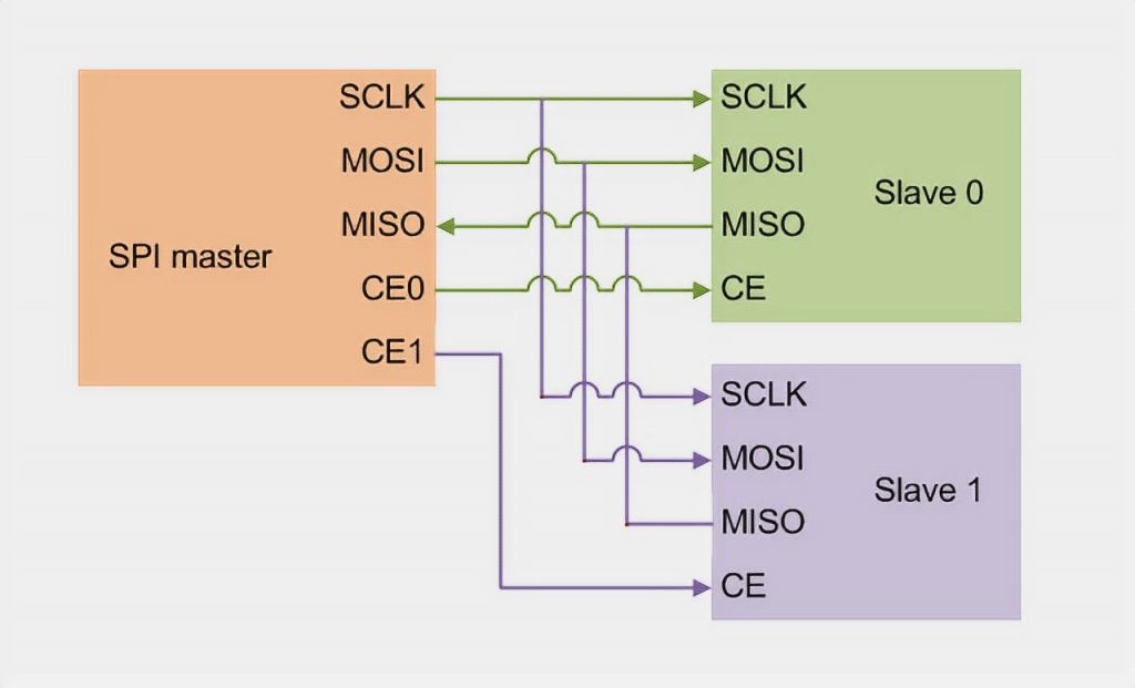
The peripheral device (Slave) communicates with the Master when there is a low signal level on the SS output. Otherwise, data from the Master device will be ignored. This architecture allows interacting with several SPI devices connected to the same bus: MISO, MOSI, and SCK.
Interaction SPI Devices
Interaction of the devices begins when a low signal level is fed to the SS output.
Before you start, you must determine:
- Which bit should start the shift – with the senior or the junior. The order is adjusted using the
SPI.setBitOrder()function. - Determine the level at which the SCK line should be located if there is no clock pulse. Adjusted by the
SPI.setDataMode()function. - Select the data transfer rate. Determined by the
SPI.setClockDivider()function.
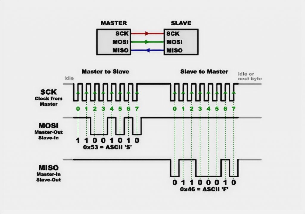
The next step is to determine in which mode the information transfer will take place. The choice of the mode is determined by such indicators as polarity and phase of the clock pulse. If the level is low, 0 shall be recorded, and high – 1. There are four modes in total:
- Mode 0: SPI_MODE0: polarity (CPOL) 0, phase (CPHA) 0.
- Mode 1: Polarity 0, Phase 1.
- Mode 2: polarity 1, phase 0.
- Mode 3: polarity 1, phase 1.
Initially in Arduino, the data are transmitted by the senior bit forward, but before you start to clarify this in the documentation. The modes may be demonstrated in the picture.
There are two types of connection in the SPI interface: independent and cascading. In the first case, when connecting, the Master addresses each connection individually; in the second case, the connection takes place one by one, i.e., cascade.
Connecting SPI to Arduino
The Arduino board already contains special outputs for connecting the SPI interface. These same pins are repeated in the ICSP interface. This connector does not have SS – originally provided that the Arduino microcontroller will act as a master device. If you want to use it as a slave, you can use any digital pin as an SS.
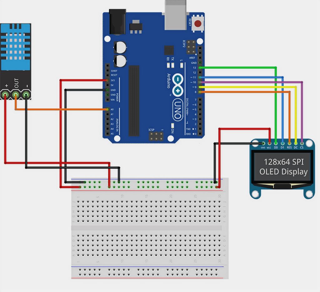
This illustration shows the option of connecting an OLED-screen via SPI to an Arduino.
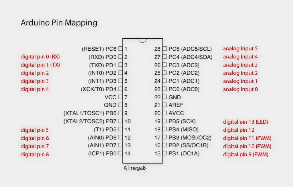
For each model of Arduino, there are different SPI pins. These conclusions:
- Uno: MOSI corresponds to pin 11 or ICSP-4, MISO – 12 or ICSP-1, SCK – 13 or ICSP-3, SS (slave) – 10.
- Mega1280 or Mega2560: MOSI 51 or ICSP-4, MISO 50 or ICSP-1, SCK 52 or ICSP-3, SS (slave) 53.
- Leonardo: MOSI – ICSP-4, MISO -ICSP-1, SCK -ICSP-3.
- Due: MOSI – ICSP-4, MISO -ICSP-1, SCK -ICSP-3, SS (master) – 4, 10, 52.
The latest Arduino Due controller expands the user’s capabilities and allows more tasks than other microcontrollers. For example, you can automatically control the slave device and automatically select different configurations (clock frequency, mode, etc.).
SPI Arduino Library
To work on, Arduino created a separate library that implements SPI. Before starting the code, you must add SPI.h to include the library.
Basic functions:
begin()andend()– to turn on and off. During initialization, SCLK, MOSI, and SS lines are configured for output, feeding a low level to SCLK, MOSI, and a high level to SS. The end() function does not change the line levels. It is necessary to turn off the block related to the Arduino board interface.setBitOrder(order)– sets the order in which bits of information are sent (MSBFIRST – high bit priority, LSBFIRST – low bit priority).setClockDivider(divider)– set the main frequency dividers. You can set dividers 2, 4, 8, 16, 32, 64, and 128. It is written as follows – SPI_CLOCK_DIVn, where n is the selected divider.setDataMode(mode)– select one of the four working modes.transfer(value)– implementation of byte transfer from the master device and the byte’s return, which is received from the slave device.shiftIn(miso_pin, sclk_pin, bit_order)andshiftOut(mosi_pin, sclk_pin, order, value)– accept and send data, you can connect to any digital pins, but before that, you need to configure them yourself.
Advantages and Disadvantages of SPI
Advantages
- Ability to transmit large data, not limited to the length of 8 bits.
- Simplicity in software implementation.
- The simplicity of hardware implementation.
- Need fewer outputs than for parallel interfaces.
- Only the speed of devices limits the maximum clock frequency.
Disadvantages
- A larger number of pins compared to I2C.
- A slave cannot control information flow.
- Lack of standard error detection protocol.
- Many interface implementation methods.
- Lack of confirmation of receiving information.
Example of Using SPI Arduino in a Project with a Pressure Sensor
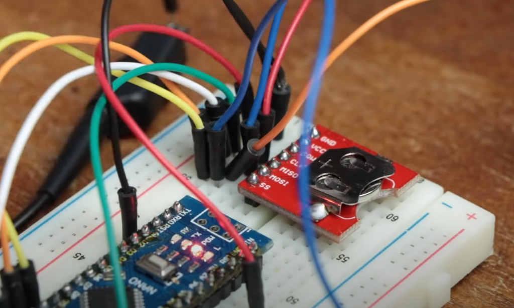
We need an Arduino, a pressure sensor, a model board, and wires for the project. An example of a sensor connection is shown in the picture.
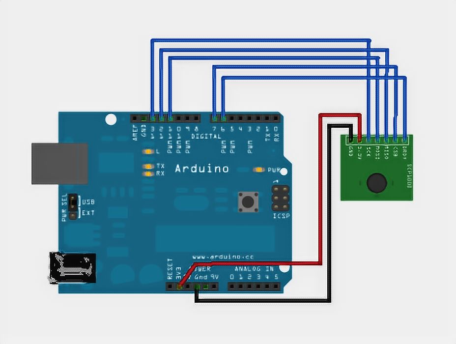
With the SCP1000 sensor, it is possible to recognize such parameters as pressure and temperature and transmit these values through SPI.
Basic Elements of the Program Sketch
First of all, the sensor registers are written in the code using setup(). Several values are returned from the device – one in 19 bits for the resulting pressure, another in 16 bits – for temperature. This is followed by reading two temperature bytes and reading the pressure in two steps. First, the program takes three high bits, then the next 16 bits, and then using a bit shift to combine these two values into one. The real pressure is a 19-bit value divided by 4.
const int PRESSURE = 0x1F; // the first stage of pressure determination (three high bits are detected)
const int PRESSURE_LSB = 0x20; // second step, which defines 16 bits for pressure
const int TEMPERATURE = 0x21; //16 bit for temperature
The following code element is used to read temperature data and convert it into degrees Celsius:
int tempData = readRegister(0x21, 2);
float realTemp = (float)tempData / 20.0; // to determine the real value of temperature in Celsius, you need to divide the resulting number by 20
Serial.print ("Temp=");
Serial.print(realTemp);

// Reading pressure bits and combining them:
byte pressure_data_high = readRegister(0x1F, 1);
pressure_data_high &= 0b00000111;
unsigned int pressure_data_low = readRegister(0x20, 2);

long pressure = ((pressure_data_high << 16) | pressure_data_low) / 4; // Pascal pressure detection.
Advanced SPI Features on Arduino Due
There are some features of working with the SPI interface on Arduino Due boards. In addition to the basic functions and methods applicable to all Arduino boards, the SPI library provides several additional methods. These methods implement the hardware capabilities of SAM3X microcontrollers and provide the developer with advanced features:
- automatic control of the slave device selection process;
- automatic control of SPI interface configurations for different devices (clock frequency, data transfer mode, etc.). This allows each slave device to have its own set of settings automatically applied at the beginning of transmission.
Arduino Due has three separate outputs (4, 10, and 52) to control peripheral devices’ SS lines.
How to Use SPI on Arduino – A Comparative Guide
In this table, we compare various indicators of SPI implementation on Arduino boards to help you understand the differences and make informed decisions for your projects.
| Indicator | Arduino Uno | Arduino Mega 2560 | Arduino Due |
|---|---|---|---|
| Number of SPI Pins | 3 (SS, MOSI, MISO) | 3 (SS, MOSI, MISO) | 4 (SS, MOSI, MISO, SCK) |
| Maximum Clock Speed (MHz) | 4 | 4 | 84 |
| Buffer Size (bytes) | 32 | 64 | 64 |
| Supported Hardware SPI | Yes | Yes | Yes |
| Supported Software SPI | Yes | No | Yes |
Explanation:
- Number of SPI Pins: Indicates the number of pins dedicated to SPI communication on each Arduino board. Arduino Uno and Arduino Mega 2560 have 3 pins, while Arduino Due has 4 pins.
- Maximum Clock Speed (MHz): Represents the maximum clock speed (in megahertz) supported by each board during SPI communication. Arduino Due offers the highest clock speed at 84 MHz.
- Buffer Size (bytes): Shows the size of the buffer (in bytes) used for SPI data transmission on each board. Arduino Uno and Arduino Mega 2560 have a buffer size of 32 bytes, whereas Arduino Due has a larger buffer of 64 bytes.
- Supported Hardware SPI: Indicates whether the board supports hardware SPI. All three boards (Arduino Uno, Arduino Mega 2560, and Arduino Due) support hardware SPI.
- Supported Software SPI: Shows whether the board supports software SPI. Arduino Uno and Arduino Due support software SPI, but Arduino Mega 2560 does not.
Please note that the SPI implementation and capabilities may vary across different Arduino models, and this table provides a general comparison for a few popular ones. Make sure to refer to the specific datasheet and documentation for each Arduino board to get detailed information on SPI usage and limitations.
Сonclusions
SPI screens and sensors are often found in Arduino projects, so you need to know how this protocol works. There is nothing complicated in the connection of SPI devices. The main thing is correctly connecting wires and using the standard library methods in the necessary sequence. For some devices, such as SD cards or OLED – screens, there are no alternatives, in principle.


