
At present, there is unprecedented interest in the construction of various flying mechanisms – drones, gliders, helicopters, etc. Now it is easy to construct them yourself thanks to many materials on them on the Internet. All these flying mechanisms use for their movement so-called brushless (brushless DC motors). What are such motors? Why are they now used in various flying drones? How to correctly buy such a motor and connect it to a microcontroller? What is ESC, and why will we use it? The answers to all these questions you will find in this article.
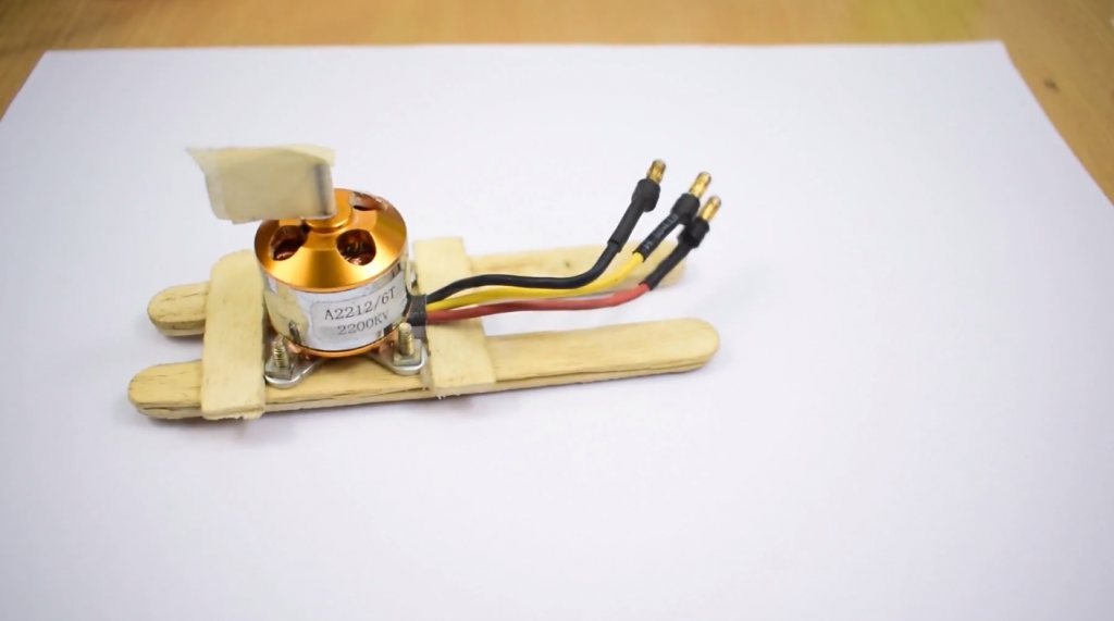
This article will look at controlling the speed of a Sensorless BLDC outrunner motor (A2212/13T), often used in drone construction, using an ESC (Electronic Speed Controller) and an Arduino board.
How Brushless (BLDC) Motors Work
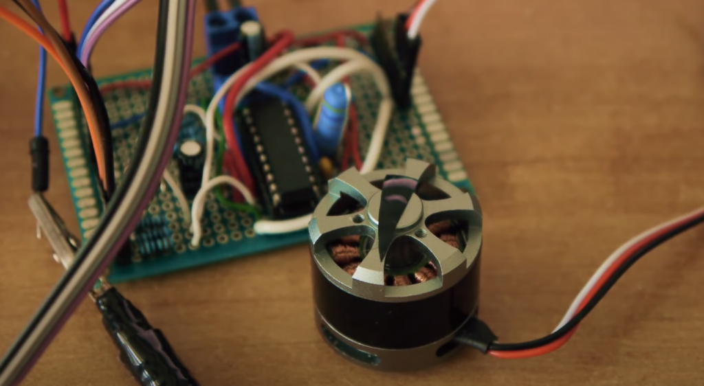
BLDC motors are now often used in ceiling fans and electric moving vehicles because of their smooth rotation. Unlike other DC motors, BLDC motors are connected with three wires coming out of them, with each wire forming its own phase, which means you get a three-phase motor.
Although BLDC motors are DC motors, they are controlled by a pulse sequence. The ESC (Electronic Speed Controller) is used to convert the DC voltage into a pulses sequence and distribute them over the three leads. At any one time, only two phases are energized, i.e., the electric current enters the motor through one phase and leaves it through the other. During this process, the coil inside the motor is energized, causing the magnets to align with the energized coil. The ESC controller then energizes the other two wires (phases), and this process of changing the wires that are energized continues continuously, causing the motor to rotate. The speed at which the motor rotates depends on how quickly power is applied to the motor coil, and the direction of rotation depends on the order in which the phases that are alternately energized are swapped.
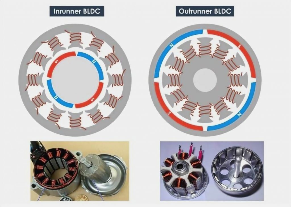
There are different types of BLDC motors – let’s look at the main ones. There are Inrunner and Outrunner BLDC motors. In Inrunner motors, the rotor magnets are inside the stator with windings, while in OutRunner motors, the magnets are outside and rotate around a stationary stator with windings. That is, in the Inrunner (most DC motors are designed according to this principle), the axis inside the motor rotates, and the shell remains stationary. In the OutRunner, the motor itself rotates around the axis with the coil, which remains stationary. OutRunner motors are particularly useful for electric bicycle applications because the motor’s outer shell directly drives the bicycle wheel, eliminating the need for a clutch mechanism. OutRunner motors provide more torque, making them also the ideal choice for electric propulsion and drone applications. This article will also be looking at connecting an OutRunner type motor to an Arduino board.
Note: there is also a BLDC motor type called coreless, which is used in “pocket drones.” These motors work on slightly different principles, but it is beyond the scope of this article to review the principles of their operation.
There are BLDC motors with sensors and without sensors. For BLDC motors, which rotate smoothly, without jerks, feedback is necessary. Therefore, the ESC controller must know the positions and poles of the rotor magnets in order to power the stator correctly. This information can be obtained in two ways: the first is by placing a Hall sensor inside the motor. The Hall sensor will detect the magnet and send this information to the ESC controller. This type of motor is called Sensor BLDC and is used in electric moving vehicles. The second method of detecting the magnets’ position is by using the inverse EMF (electromotive force) generated by the coils while the magnets are crossing them. The advantage of this method is that it does not require the use of any additional devices (Hall sensor) – the phase wire itself is used as feedback due to the presence of the inverse EMF. This method is used in the motor discussed in our article, and it is the one most often used in drones and other flying devices.
Why Do Drones and Helicopters Use BLDC Engines?
There are many different types of drones now – two-bladed, four-bladed, etc. But they all use BLDC engines. Why BLDC motors, since BLDC motors are more expensive than conventional DC motors?
There are several reasons for this:
- High torque, which is very important to get the flying vehicle off the ground;
- these motors are available in OutRunner format, which does away with the clutch in the drone design;
- low level of vibration during operation, which is very important for the drone to hover still in the air;
- a good power-to-weight ratio of the motor. This is very important for use on flying mechanisms so that all elements of its design have as little weight as possible. A normal DC motor that provides the same torque as a BLDC motor will be at least twice as heavy as a BLDC motor.
Why Do You Need an ESC Controller?
As we already know, BLDC motors require some kind of controller to function, which converts the DC voltage from the battery into a sequence of pulses applied in a specific order to the motor wires (phases). This controller is called ESC (Electronic Speed Controller). This controller’s main responsibility is to properly supply power to the BLDC motor wires so that the motor rotates in the correct direction. This is done by reading the back EMF from each wire and supplying power to the coil as the magnet crosses it. Internally the ESC controller contains quite a lot of different electronics, and if you wish, you can study its construction in detail on the appropriate materials on the Internet. Here we will take a brief look at only the basic components of its design.
The speed control is based on PWM (Pulse-width modulation). The ESC controller can control the BLDC motor’s speed by reading the PWM signal from its orange wire. It is very similar to a servo motor. The PWM signal sent to the ESC controller must have a period of 20ms, and the fill factor of this PWM signal will determine the rotation speed of the BLDC motor. Since exactly the same principle is used to control the servo motor’s angle of rotation, we can use the library to control the BLDC motor. If you have not encountered this principle before, you can read an article about connecting a servo motor to an Arduino board.
Battery Eliminator Circuit (BEC) is a battery eliminator circuit. Almost all ESC controllers come with this circuit. As the name suggests, this circuit eliminates the need for a separate battery to power the microcontroller, meaning that in this case, we don’t need a separate power supply for the Arduino board – the ESC controller itself will provide the Arduino board with a regulated +5V supply voltage. Different ESC controllers use different circuits to regulate this voltage, but a linearly regulated circuit is common in most cases.
Firmware. Each ESC controller contains in its ROM a built-in application program written by the manufacturer of the controller. This program largely determines the logic of the controller operation. The most popular firmware for ESC controllers are Traditional, Simon-K and BL-Heli. The user can change this program, but we will not discuss this issue in this article.
Some Terms Used in the Subject of BLDC and ESC
When studying BLDC motors and ESC controllers’ principles, you may come across some of the terms used in this topic. Let’s briefly review the main of these terms.
Braking – determines how fast a BLDC motor can stop its rotation. This is especially relevant for flying vehicles (drones, helicopters, etc.) because they have to frequently change the number of engine revolutions per minute to maneuver in the air.
Soft Start – this ability is especially important for BLDC engines when the torque from the engine to the actuator (wheel, propeller, etc.) is transmitted through a gear mechanism, usually consisting of gears. A soft start means that the motor will not start rotating at maximum speed immediately but will gradually increase its speed, regardless of the speed at which the actuating torque builds up. A soft start greatly reduces the wear and tear on the gears in the gear train.
Motor Direction – Normally, the direction of rotation of BLDC motors does not change during operation. However, during the assembly and testing of the product, it may be necessary to change motor rotation direction. Usually, this can be done by simply reversing any two motor wires.
Low Voltage Stop. Normally BLDC motors are calibrated, so that rotation speed is constant for the same level of actuation. However, this is difficult to achieve because the voltage of the battery supply decreases over time. To prevent this, the ESC controllers are usually programmed to stop the BLDC motor when the battery voltage drops below a certain limit. This feature is especially useful when using BLDC motors in drones.
Response time – Refers to the motor’s ability to quickly change rotation speed when the control action changes. The lower the response time, the better the motor control.
Advance. This problem is a kind of “Achilles’ heel” for brushless motors. All BLDC engines have at least a small similar bug. This problem is caused by the fact that when the stator coil is energized, the rotor moves forward because there is a permanent magnet on it. And when the control voltage is removed from that coil (to feed it to the next coil), the rotor moves forward a bit farther than the motor logic allows. This unwanted advance of the motor is called “Advance” in the English-language literature and can lead to unwanted vibrations, heat, and noise when the motor is running. Therefore, good ESC controllers try, if possible, to eliminate this effect in BLDC motor operation.
Circuit Operation
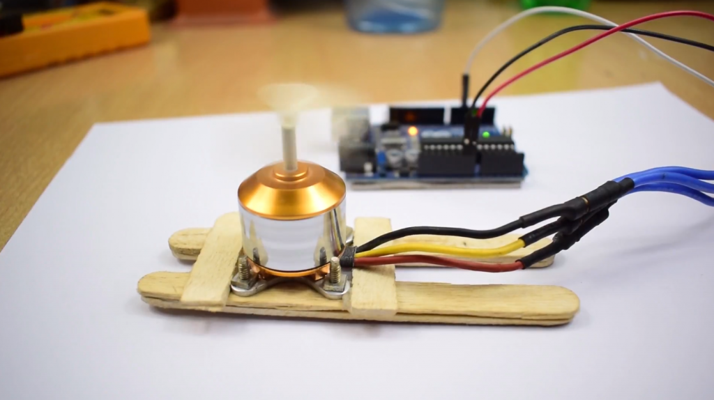
The wiring diagram of the BLDC motor and the ESC controller to the Arduino board is shown in the following picture.
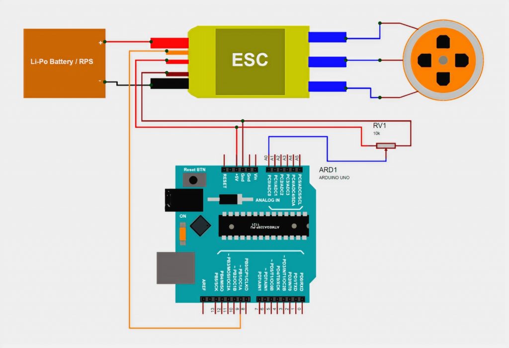
As you can see, the circuit is quite simple. The ESC controller needs a power supply with 12V and at least 5A current. You can use an adapter or a Li-Po battery to power the circuit. The three phases (wires) of the BLDC motor must be connected to the three output wires of the ESC controller – no matter what order.
The BEC (Battery Eliminator circuit) in the ESC controller will provide (regulate) a +5V DC voltage on its own so that it can be used directly to power the Arduino board. The circuit uses a potentiometer connected to pin A0 of the Arduino board to control the motor’s speed.
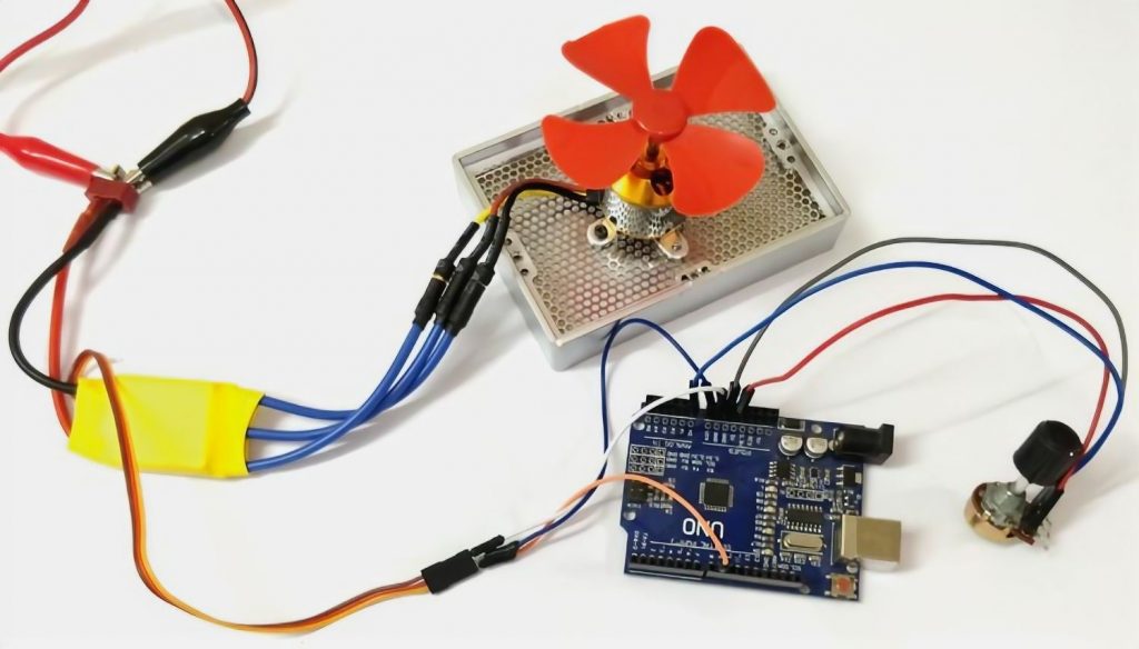
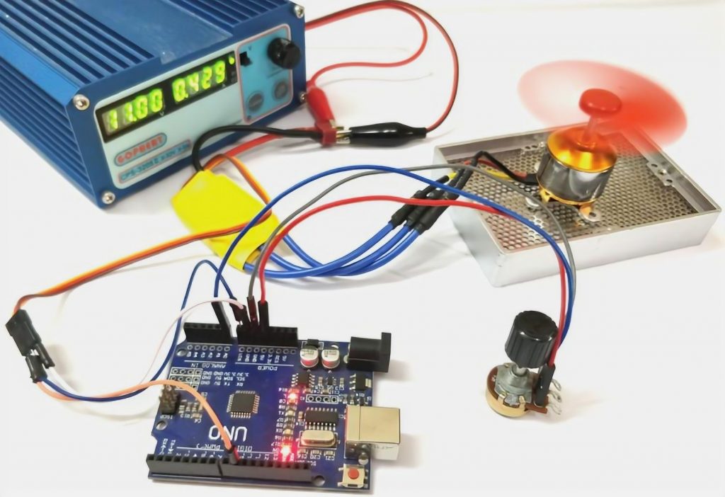
The appearance of the assembled construction is shown in the following picture.
Explanation of the Arduino Program
The complete code of the program is given at the end of the article. Here we will only look at the main parts.
To control the BLDC motor, we will form a PWM signal with a frequency of 50 Hz and a variable from 0 to 100% duty cycle. A potentiometer will control the fill factor value. That is, by turning the potentiometer, we will control the speed of the motor. As already mentioned, controlling a BLDC motor is very similar to controlling a servo motor with 50 Hz PWM, so in this case, we will use the same library we used to control the servo motor. Suppose you are a beginner in learning the Arduino platform. In that case, we recommend you study PWM signal generation’s principles in Arduino and the connection of the servomotor to the Arduino board before reading this article further.
The PWM signal can only be generated on the Arduino board’s digital pins, which are marked with the ~ symbol. In our circuit, we will control the ESC controller from pin 9 of the Arduino board, so with the following command, we will attach the ESC controller to this pin:
ESC.attach(9);
The PWM fill factor (0 to 100%) is controlled by the position of the potentiometer knob. So when we have 0V on the potentiometer output (0 on the ADC output), we will have a fill factor of 0, and when we have 5V on the potentiometer output (1023 on the ADC output), we will have a PWM fill factor of 100%. So we will use a function that will read the value from the ADC output of pin A0.
int throttle = analogRead(A0);
Then we have to convert this value (it will be in the range of 0 to 1023) to a range of 0 to 180. A value of 0 will be 0% PWM fill factor, and a value of 180 will be 100% PWM fill factor. The conversion of the value from the range 0-1023 to the range 0-180 will be done using the function:
throttle = map(throttle, 0, 1023, 0, 180);
Next, we have to pass this value to the motor control function to generate the appropriate PWM signal on the contact we need. Since we gave our servo object the name ESC, the command to control it will look like this:
ESC.write(throttle);
Testing How the Circuit Works
Make all the necessary connections in the circuit, load the program into the Arduino board, and power up the ESC controller. Make sure that your BLDC motor is securely mounted. Otherwise, it will bounce while spinning. When you apply power to the ESC controller, you will hear a greeting tone, and it will make this sound until a control signal of the set level (within the specified limits) is received. Start turning the potentiometer knob gradually until the potentiometer output voltage is different than 0, and the sound will stop. This means you have given the minimum allowable level signal to the PWM controller. As you turn the potentiometer knob further, the motor will start to rotate slowly. As you turn the potentiometer knob further and increase the voltage at its output, the speed of the motor will increase. When the voltage reaches the upper allowable limit, the motor will stop. Afterward, you can repeat the whole process again.
The Source Code of the Program (Sketch)
#include <Servo.h> //use the servo library to generate the PWM signal
Servo ESC; //name our servo object. In our case, it will be the name of ESC
void setup()
{
ESC.attach(9); //"attach" the ESC controller to pin 9 of the Arduino board
}
void loop()
{
int throttle = analogRead(A0); //read voltage from the potentiometer output
throttle = map(throttle, 0, 1023, 0, 180); //convert the values from the range 0-1023 from the ADC output into the range 0-180 because servomotors can only operate in the range 0-180
ESC.write(throttle); //generate PWM signal with necessary filling ratio
}
If you have any questions about this program’s source code, you can ask them in the comments of this article.


I am having some problem regarding calibration and running of BLDC motors using Xbox Redgear controller and USB Host shield on Arduino UNO.By using XBOXUSB.h library I am able to control other motors , but it is giving me problem with BLDC motors. Any suggestions?
If you’re experiencing issues with calibrating and running BLDC motors using an Xbox Redgear controller and a USB Host shield on Arduino UNO, there could be a few possible reasons for the problem. Here are some suggestions to help you troubleshoot the issue:
1. Power Supply: Make sure you have a sufficient power supply for your BLDC motors. These motors typically require higher voltage and current compared to other types of motors. Ensure that your power supply can deliver the necessary voltage and current to run the motors.
2. Motor Driver: Check if you are using an appropriate motor driver for your BLDC motors. BLDC motors require specific motor drivers that can handle the motor’s three phases. Make sure the motor driver you’re using is compatible with BLDC motors and can handle the required voltage and current.
3. Wiring: Double-check your wiring connections. Ensure that you have connected the motor driver to the Arduino correctly, following the manufacturer’s instructions. Verify that the motor phases are connected to the correct terminals on the motor driver.
4. Motor Control Signals: BLDC motors require specific control signals to operate correctly. Confirm that you are sending the appropriate control signals to the motor driver from the Arduino. Ensure that the control signals are compatible with the motor driver and correctly correspond to the motor’s required sequence.
5. Calibration: BLDC motors may require calibration to function correctly. Consult the motor’s datasheet or manual for the calibration procedure. Follow the instructions precisely to calibrate the motor properly before attempting to run it.
6. Code and Library: Review your code and the XboxUSB library you’re using. Ensure that you’re using the correct functions and commands for controlling BLDC motors. Check if there are any specific instructions or examples provided by the library’s documentation for using BLDC motors.
7. Debugging: Use debugging techniques to identify the problem. Add debug print statements to your code to check if the controller inputs are being read correctly and if the motor control signals are being sent to the motor driver as intended. This can help you pinpoint where the issue might be occurring.
8. Compatibility: Confirm that the Xbox Redgear controller and the USB Host shield are compatible with the XboxUSB library and your Arduino UNO board. Check the library documentation and ensure that all the required hardware is supported.
9. Consultation and Support: If you’ve tried all the above steps and are still encountering issues, consider reaching out to the manufacturer or community forums specific to the Xbox Redgear controller, USB Host shield, or BLDC motors. They may provide additional guidance or support based on their experience.
Remember to exercise caution when working with motors and electrical components to avoid any safety hazards.