
Another useful device that is often used in modern devices is a temperature sensor. Even your computer has several temperature sensors, with which the system monitors the overheating of key components – processor, graphics card, power supply, and other components. The most popular example of a home temperature sensor is a thermostat. It is a device that constantly monitors the air temperature, and regulates the power supply to the heating system. A related example is a boiler for heating water.
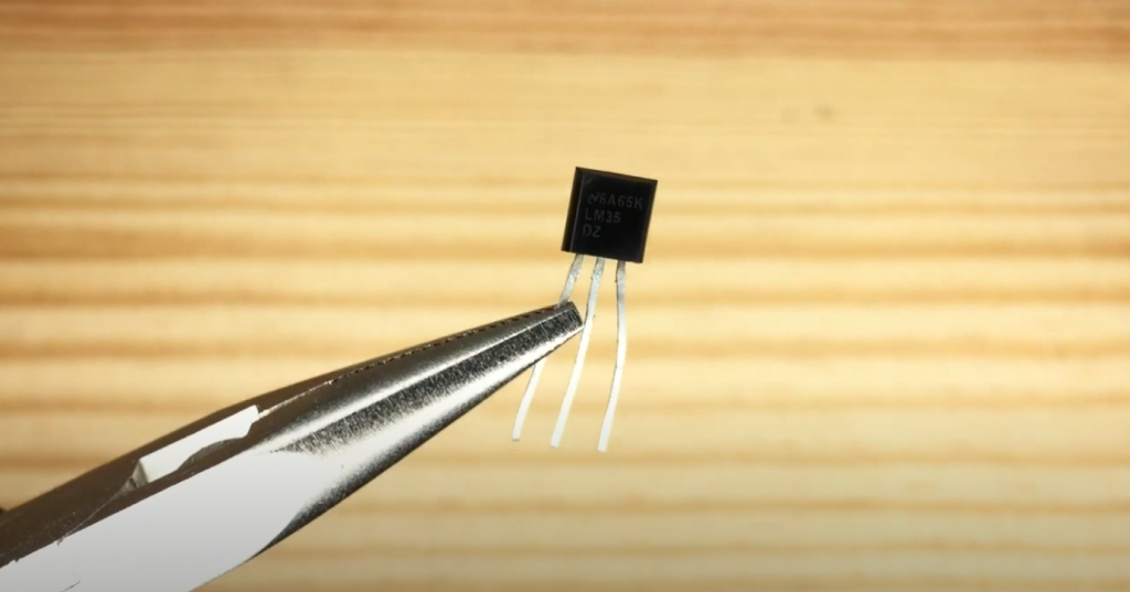
In this tutorial, we use the LM35 sensor. You can use any other similar sensor instead: TMP35, TMP37, LM335, and similar. The sensor looks like an ordinary transistor:
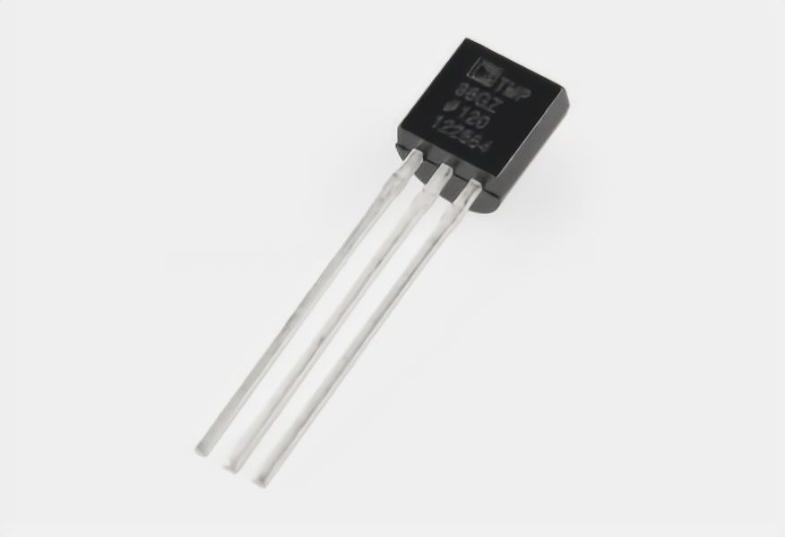
It can be easily confused, so I recommend that you always read the markings on such devices carefully (and in fact, always read first, then plug it in. This particular sensor has the following characteristics:
- supply voltage: 2.7 to 5.5 V;
- mistake: 2 degrees;
- temperature measured: from 50 °F to 257 °F;
- current consumption: 50 µA.
Advantages of the LM35 sensor: linear dependence of the output signal (temperature/voltage), low output resistance, built-in calibration circuit. The sensor can work in the range from -67 ºF to 302 ºF.
Connecting to Arduino
The LM35 sensor has three pins (three legs). If you look at the sensor from the side of these pins and slice upwards, as shown in the picture:
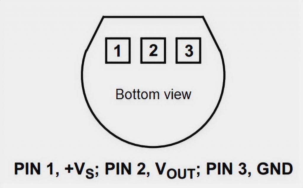
The left side is the positive (+2.7V to 5.5V),
in the center is the output to the controller,
and to the right is the negative power contact (ground).
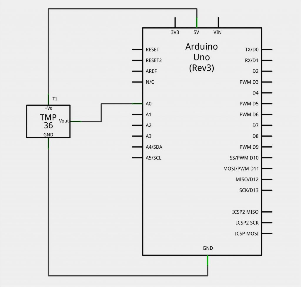
The sensor is analog, so its output is not a 0 or 1, but a voltage in the range of 0 to 5 volts. Consequently, we have to remember the analog-to-digital conversion (ADC) of the signals. Keeping in mind that the Arduino Uno has six analog inputs (A0-A5), we connect our sensor according to the following diagram:
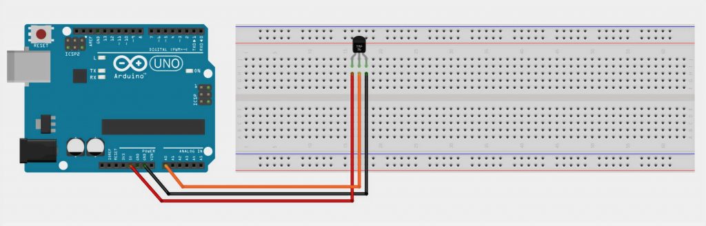
Schematic Diagram of LM35 and Arduino
The Program
Now you connect our temperature sensor to the Arduino and start writing our program. The first thing we do is to output the raw signal from the analog input into the serial port just to understand how the value of input A0 changes. We need a simple code:
int raw = 0;
float temp = 0;

void setup() {
    Serial.begin(9600);
    pinMode( A0, INPUT );
}

void loop() {
    raw = analogRead(A0);
    temp = ( raw/1023.0 )*5.0*1000/10;
    Serial.println(temp);
    delay(1000);
}
Attention, math! In the program you can notice the expression:
temp = ( raw/1023.0 )*5.0*1000/10;
This is needed to convert the analog signal from the sensor into degrees Celsius. Here’s the thing. All analog sensors have an important characteristic – the ratio of the number of volts to the unit of the measured value. For example, in the specification of our LM35 sensor, it is written that each degree of measured temperature corresponds to 10 millivolts of voltage at the output. Based on this reasoning, we first convert the value read with analogRead to a number of Volts:
Volts = (ADC value / 1023) * 5
This procedure is called normalization. Here 1023 is the maximum value that the 10-bit ADC built into the Arduino Uno can return us.
5 is the operating voltage of the ADC.
Then we convert these volts to degrees Celsius:
degrees = (volts * 1000) / 10
Convert the volts to millivolts (*1000), and divide by 10 (the same number from the datasheet!).
In general, even if nothing is clear, we load the program on the Arduino and observe the ambient temperature. For example, in our lab, the sensor estimated the temperature as follows:
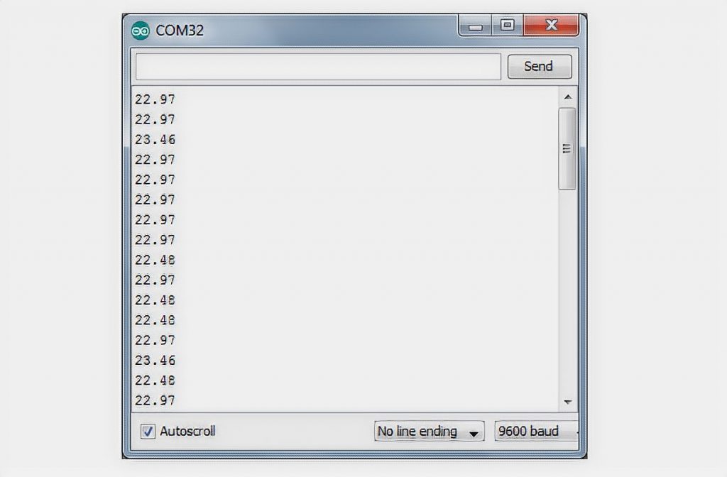
That’s a pretty good value. And now let’s bring the device to an open window (it’s winter -10°C outside):
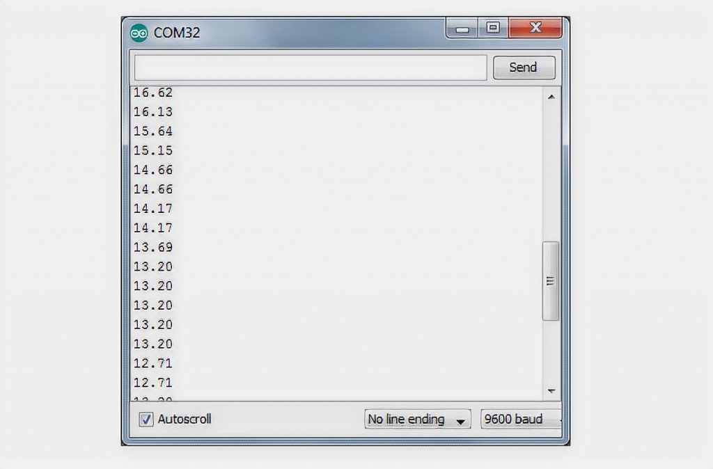
It works! The sensor immediately registers a decrease in temperature.
Making the Thermostat
Let’s now add some action to the program which will take place if the temperature drops below our specified threshold. Let this threshold be 15°C. The easiest thing we can do is to light the LED #13 on the Arduino. Here is the program:
int raw = 0;
float temp = 0;

void setup() {
    pinMode( A0, INPUT );
}

void loop() {
    raw = analogRead(A0);
    temp = ( raw/1023.0 )*5.0*1000/10;
    if (temp < 15)
        digitalWrite(13, HIGH);
    else
        digitalWrite(13, LOW);
    delay(1000);
}
Someone forgot to close the window – the temperature dropped sharply below 15 – the LED lights up. We close the window, actively breathe – the LED goes off. Imagine that you are not lighting the LED, but you are feeding a signal to a relay that turns on a heater in the room. You have a thermostat at your fingertips!
By changing the program a little bit you can monitor not lowering, but exceeding the set level. For example, it will be convenient to monitor the temperature in, say, a server room, and when the temperature rises to 40 degrees, turn on the hood!
Consideration
More and more often digital temperature sensors are used in modern devices, such as the well-known DIY environment DS18B20 sensor. It is easy to connect to an Arduino with only one signal wire – one wire.


Hello!
I connected the LM35 module to the Arduino and in the port, the monitor ran numbers, but when I bring a burning match to the sensor, the values of running numbers began to decrease, although logically the values should increase! I can not understand what is wrong. Please, explain briefly, where the dog is buried. Thank you.
Hello, John! Try reversing the polarity of the LM35 to the Arduino.