
Many Arduino projects require you to track and record the timing of certain events. A real-time clock module equipped with an extra battery allows you to store the current date without depending on the power supply of the device itself. This article will talk about the most common RTC modules, DS1307, DS1302, DS3231 which can be used with the Arduino board.
Real-Time Clock Modules in Arduino Projects
The clock module is a small board usually containing one of the DS1307, DS1302, DS3231 chips. Such boards are often used to keep track of time, date, day of the week and other chronometric parameters. The modules work from an autonomous power supply – batteries, rechargeable batteries, and continue counting even if the Arduino has lost power. The most common clock models are the DS1302, DS1307, DS3231. They have based on an RTC (real-time clock) module connected to the Arduino.
 It can generate seconds, minutes, hours, day, date, month and year and provide time until 2100, and with leap year compensation. Working voltage: 3.3 -. 5 .5 V.
The clock counts in units that are convenient for the average person – minutes, hours, days of the week, and others, unlike conventional counters and clock oscillators that read “ticks”. The Arduino has a special function millis(), which can also read different time intervals. But the main disadvantage of this function is that it resets to zero when the timer is on. It only reads the time. You can’t set the date or day of the week. The real-time clock modules are used to solve this problem.
The electronic circuit includes a chip, a power supply, a quartz resonator and resistors. The quartz resonator operates at 32768 Hz, which is a convenient frequency for a conventional binary counter. The DS3231 circuitry has built-in quartz and thermal stabilization that allow for high accuracy values.
Comparison of Popular DS1302, DS1307, DS3231 RTC Modules
In this table, we have listed the most popular modules and their main characteristics.
| Module | Frequency | Precision | Supported protocols |
| DS1307 | 1 Hz, 4.096 kHz, 8.192 kHz, 32.768 kHz | Depends on the quartz – typically up to 2.5 seconds per day, it is not possible to achieve accuracy better than 1 second per day. Accuracy also depends on temperature. | I2C |
| DS1302 | 32.768 kHz | 5 seconds per day | I2C, SPI |
| DS3231 | Two outputs – first at 32.768 kHz, second programmable from 1 Hz to 8.192 kHz | ±2 ppm at temperatures from 32 °F to 104 °F (0 °C to 40 °C). ±3.5 ppm at temperatures from -40 °F to 185 °F (-40 °C to 85 °C). Temperature accuracy ±37 °F (±3 °C) |
I2C |
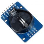
DS1307 Module
The DS1307 is a module that is used for time counting. It is based on the DS1307ZN chip and powered by a lithium battery to realize autonomous operation for a long time. The battery is mounted on the backside of the board. The module has an AT24C32 chip – it is a 32kb non-volatile EEPROM memory. Both chips are interconnected via the I2C bus. The DS1307 has low power consumption and contains a 2100 year clock and calendar.
The module has the following parameters:
- A power supply is 5V;
- Operating temperature range from -40 °F to 185 °F (-40 °C to 85 °C);
- 56 bytes of memory;
- It implements 12 and 24-hour modes;
- Support for I2C interface.
Lithium battery LIR2032;
The module is justified in cases where the data is read rather rarely, at intervals of a week or more. This allows you to save on power because, in the case of uninterrupted use will have to spend more voltage, even with the presence of the battery. The presence of memory allows you to record various parameters (e.g. temperature measurement) and read the module’s information.
Interaction with other devices and exchanging information with them is done using the I2C interface with contacts SCL and SDA. The circuit is equipped with resistors, which allow providing the required signal level. There is also a special place on the board for mounting a DS18B20 temperature sensor. The contacts are distributed into two groups, pitch 2.54 mm. The first group of contacts contains the following pins:
- DS – pin for the DS18B20 sensor;
- SCL – clocking line;
- SDA – data line;
- VCC – 5V;
- GND.
The second group of pins contains:
- SQ – 1 MHz;
- DS;
- SCL;
- SDA;
- VCC;
- GND;
- BAT – lithium battery input.
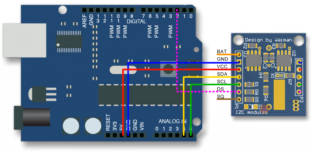
To connect to the Arduino board, you need the board itself (Arduino Uno is considered in this case), the RTC DS1307 real-time clock module, wires and a USB cable.
Four pins are used to connect the controller to the Arduino – VCC, ground, SCL, SDA… VCC from the clock is connected to 5V on the Arduino, ground from the clock is connected to ground from the Arduino, SDA is A4, SCL is A5.
You need to install the DS1307RTC, TimeLib and Wire libraries to get started with the clock module. You can also use RTCLib to work.
Checking the RTC Module
When you run the first code, the program will read the data from the module once per second. First, you can see how the program will behave if you remove the battery from the module and replace it with another while the Arduino board is not connected to the computer. You have to wait a few seconds and then remove the battery, and the clock will restart. Then you have to choose an example in the menu Examples → RTClib → DS1307. It is important to set the baud rate to 57600 bps correctly.
When the serial monitor window opens, the following lines should appear:
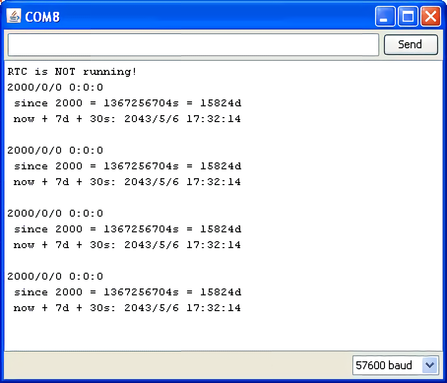
The time 0:0:0 will show. This is because the clock will lose power, and the time will stop counting. For this reason, the battery should not be removed while the module is running.
To adjust the time on the module, you need to find the line in the sketch.
RTC.adjust(DateTime(__DATE__, __TIME__));
This line will contain the computer data, which are used to firmware the real-time clock module. For correct operation, you must first check if the date and time are correct on the computer and start flashing the clock module. After setting, the monitor will display the following data:
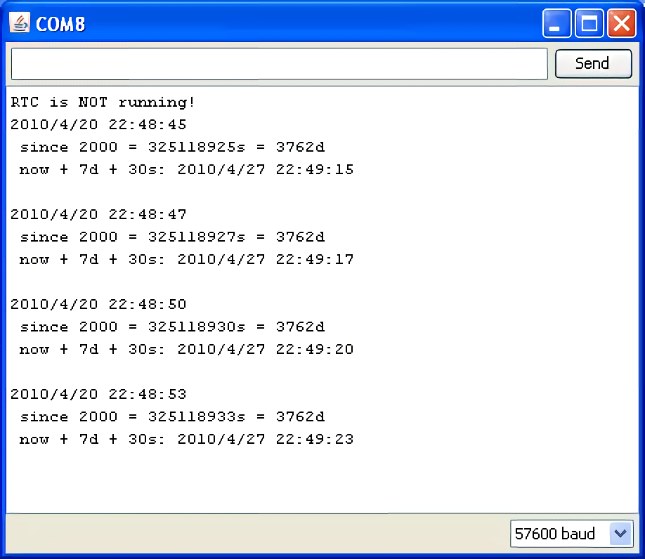
The settings are correct, and there is no need to reconfigure the real-time clock.
Read out the time. Once the module is configured, you can send out requests to get the time. The now() function is used To do this, which returns the DateTime object, which contains information about the time and date. There are several libraries that are used to read the time. For example, RTC.year() and RTC.hour() – they get information about year and hour separately. When working with them, a problem can occur: for example, a request to display the time will be made at 1:19:59. Before displaying the time 1:20:00, the clock will display the time 1:19:00, which means, in fact, that one minute will be lost. Therefore, it is reasonable to use these libraries in cases where the reading is infrequent – once every few days. There are other functions to call the time, but it is better to use now() and from it already pull out the necessary readings if you want to reduce or avoid errors.
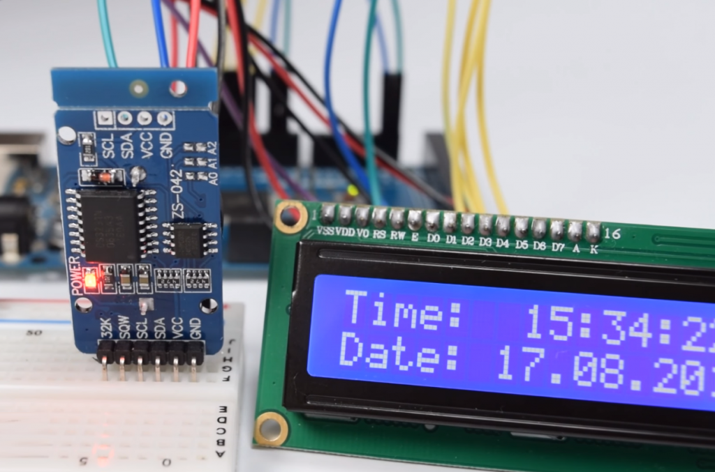
Example of a Project with i2C Clock Module and Display
This project is a simple clock, and the exact time will be shown on display. The colon between the digits will blink once every second. To implement the project, you will need an Arduino Uno board, a digital indicator, a real-time clock (in this case, the ds1307 module described above), a wiring board, a battery for the clock and wires.
The project uses a simple four-digit clock on the TM1637 chip. The device has a two-wire interface and provides eight levels of monitor brightness. It is only used to show the time in hour: minute format. The indicator is simple to use and easy to connect. It is advantageous for projects that do not require minute-by-minute or hour-by-hour verification of data. LCD monitors are used for complete time and date information.
The clock module is connected to the SCL/SDA pins that refer to the I2C bus. Ground and power must also be connected. The Arduino is connected the same way as described above: SDA – A4, SCL – A5, ground from the module to ground from the Arduino, VCC -5V.
The indicator is connected – the pins CLK and DIO are connected to any digital pins on the board.
Sketch. To write the code, you use the function setup, which allows you to initialize the clock and indicator and record the compile time. The output of the time on the screen will be done with a loop.
#include <Wire.h>
#include "TM1637.h"
#include "DS1307.h" //you need to include all of the necessary libraries to work with the clock and display.

char compileTime[] = __TIME__; //compile time.

#define DISPLAY_CLK_PIN 10
#define DISPLAY_DIO_PIN 11 //numbers from the Arduino outputs, to which the screen is connected;

void setup()

{

display.set();

display.init(); //connect and set screen.

clock.begin(); //connect the clock.

byte hour = getInt(compileTime, 0);

byte minute = getInt(compileTime, 2);

byte second = getInt(compileTime, 4); //receiving time.

clock.fillByHMS(hour, minute, second); //preparing to write to the time module.

clock.setTime(); //write received information into internal memory, start time reading.

}

void loop()

{

int8_t timeDisp[4]; //display each of the four digits.

clock.getTime();//request to get time.

timeDisp[0] = clock.hour / 10;

timeDisp[1] = clock.hour % 10;

timeDisp[2] = clock.minute / 10;

timeDisp[3] = clock.minute % 10; //different operations to get tens, units of hours, minutes, etc.

display.display(timeDisp); //display time

display.point(clock.second % 2 ? POINT_ON : POINT_OFF);//turning on and off the colon after one second.

}

char getInt(const char* string, int startIndex) {

return int(string[startIndex] - '0') * 10 + int(string[startIndex+1]) - '0'; //actions for correct time record into two-digit integer. Otherwise just a pair of characters will be displayed.

}
After that, the sketch must be loaded, and the time will be shown on the monitor.
The program can be slightly upgraded. If the power is switched off, the above-written sketch will cause that the display will show the time that was set during compilation after switching on. The setup function will calculate the time that has elapsed since 00:00:00 before the start of compilation each time. This hash will be compared to what is stored in the EEPROM, which is stored when the power is turned off.
To write and read the time to or from the non-volatile memory, you must add the functions EEPROMWriteInt and EEPROMReadInt. They are needed to check if the hash matches/mismatches the hash stored in the EEPROM.
It is possible to improve your project. If you use a liquid crystal monitor, you can do a project that will display the screen’s date and time. The connection of all elements is shown in the figure.
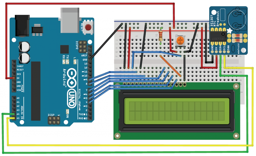
As a result, in the code, you will need to specify a new library (for liquid crystal screens, it is LiquidCrystal) and add lines to the loop() function to get the date.
The algorithm is as follows:
- Connecting all components;
- Loading the sketch;
- Checking – the time and date must change every second on the screen. If the screen time is incorrect, you must add to the script function RTC.write (tmElements_t tm). Problems with incorrectly set time are because the clock module resets the date and time to 00:00:00 01/01/2000 when shutting down;
- The write function allows you to get the date and time from the computer, and then the correct parameters will be displayed.
Conclusion
Clock modules are used in many projects. They are needed for data logging systems, in creating timers and control devices that work according to a set schedule, in household appliances. With widespread and cheap modules, you can create such projects as an alarm clock or a sensor data logger by recording the information on an SD card or by showing the time on a display screen. This article looked at typical usage scenarios and connection options for the most popular kinds of modules.


