
The ESP8266 was the real news of the last year for everyone who builds Arduino-based devices. It is a cheap microcontroller with more features than its expensive counterpart, yet compatible with AT+.
Arduino was not left out, and now this module is officially added to the list of supported by the board, and accordingly, more and more users will join the Chinese microcontroller for Wi-Fi connection. But the system needs to track the module’s location, for which one board ESP8266 will not be enough. This is where ESP8266 and SIM800L come in handy.
Possibilities to Connect the SIM800L to the ESP8266 Microcontroller
Smart homes and many crafts require notification of the board’s location, whether a remote door or a regular tracker. Here is a short list of things that you can create by combining the ESP8266 and SIM800L:
- Smart Home. Almost any technique for smart homes can be set to certain patterns when an object is approaching. But why install motion sensors if you can attach a SIM800L to the Wi-Fi board, sew in some piece of clothing microcontroller with a battery (goodness, a lot of power is not required) and automatically turn on the light or open the door when the user approaches.
- All sorts of tracking devices. We are not talking about illegal bugs or other devices that violate your privacy rights. However, the microcontroller can work separately from the Arduino, and if you attach a SIM800L to it, the total size of the device won’t exceed a matchbox. Just wrap everything in a metal case and attach it to your keys as a keychain. Finding your smartphone, keys, and even your car in the parking lot will be easier.
- Robotics and related fields. You can talk about the development of modern virtual intelligence and neural networks for a long time, but often, it is not enough for a piece of hardware to have sensors to create a map of the area and navigate in it. And if you do something like that, the GPS module comes in handy. It is convenient when paired with drones.
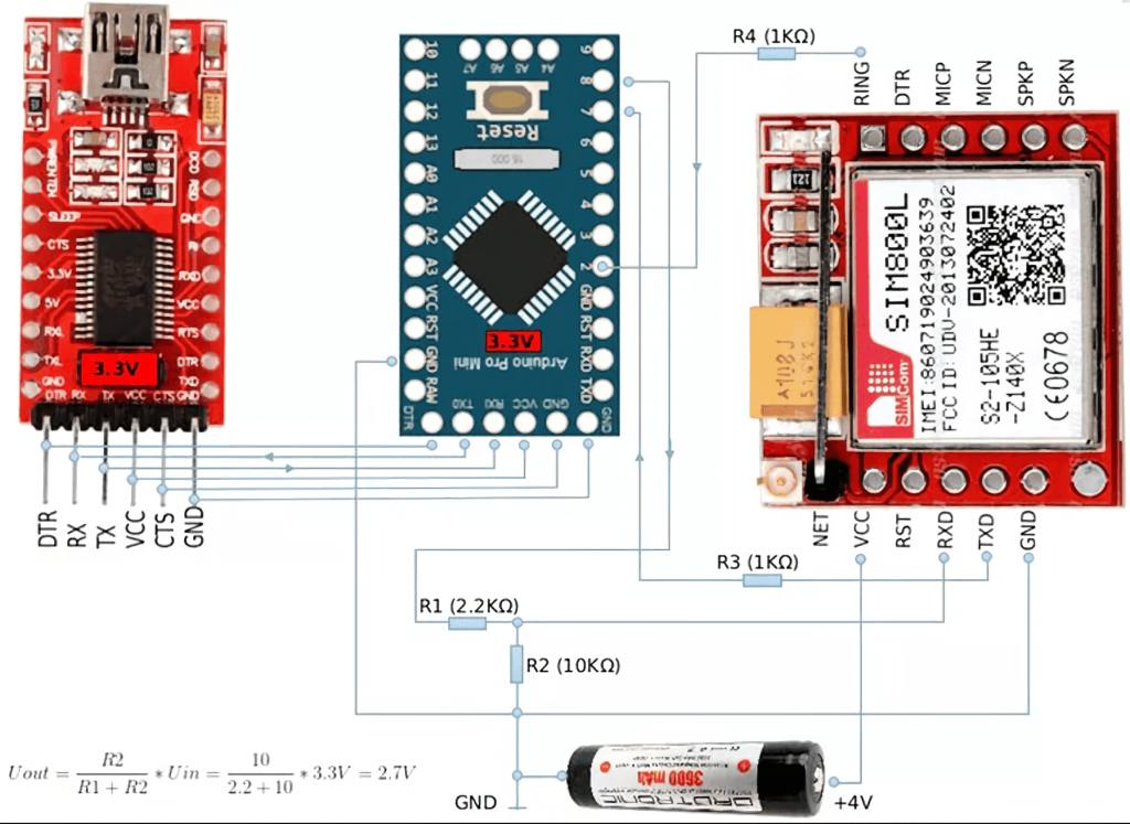
When you have decided on the project’s final goal, you need to understand the nuances of the question. The connection of the devices to the microcontroller mentioned above is the same as for standard Arduino boards. The only difference is the number of available pins. The GPS tracker requires 3.7 to 4.2 volts to operate instead of the usual 5 volts provided by the microcontroller. You have to design the circuit board accordingly and choose auxiliary power supplies accordingly. Or install transformers and resistors, depending on what else you will connect to the final system.
Once you connect the tracker to the system, you need to start it up and send the first commands. AT and AT+ are best. The module will finally start sending data and responding to your requests after these actions, so don’t worry if you have connected it. The diode is flashing, but there is no reaction to scripts. You need to activate SIM800L the first time you use it so that it has time to register on the network.
Also, do not consider SIM800L an alternative to the ESP8266, as many users on forums are sinning. If you have stumbled on such a statement, you can be sure that the author has never worked with an Arduino. First of all, comparing an auxiliary board and a microcontroller makes no sense. Not to mention that one of the devices is designed to coordinate, send and receive requests over the wireless Internet, and the other is a GSM GPRS module. Accordingly, they are an excellent complement to each other but by no means an alternative.
Wiring Diagram SIM800L to ESP8266
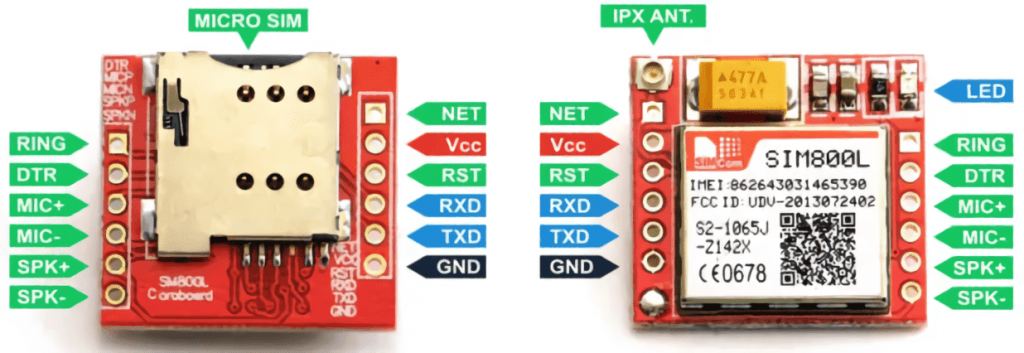
The pinout is more than standard. You connect the power pin to a power supply capable of delivering 3.7-4.2 volts or to a transformer. TX goes to the RX pin and vice versa. Once you have soldered the module and decided to test it by plugging in the power supply, the diodes will signal that it is connected correctly. Next, activate the module using the method described above, and you can use AT commands to control it. If you want to load an auxiliary library or some weighty media, it’s worth reading about connecting the memory card to the Arduino system.
First, let’s test the speed of the port and the information about the module. We use “AT+IPR?” and “AT+CPAS,” respectively. If everything is OK and the information is displayed without errors, we can continue to check and test the signal strength and the operators that the module can see.
This also opens up a lot of room for applying systems with it. If you want to write a specific script that triggers something on an incoming call, consider that the module responds with the phrase “RING” on the command line.
This kind of functionality allows you to create hundreds of self-contained control systems, up to the point that instead of fingerprints or key cards, you can open the door on a call to a specific number. But of course, for a good level of protection, it is worth prescribing a white list of numbers.
Example of Connecting the GSM Module SIM800L to the ESP8266
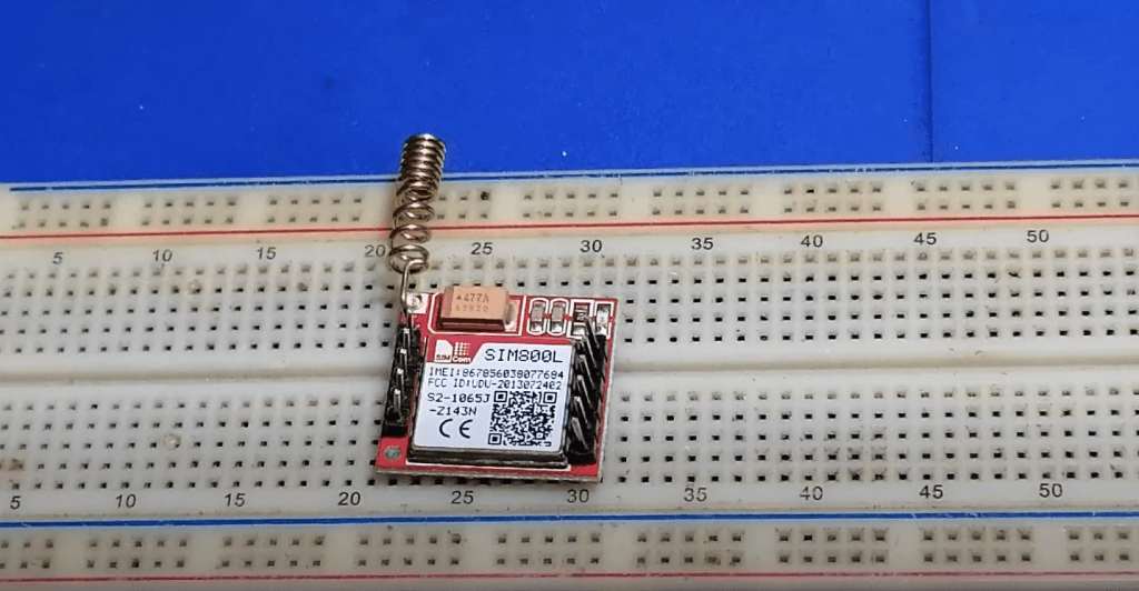
The module should start blinking after connecting and soldering on the above-described pins. The diodes will begin blinking less frequently as soon as the network authentication occurs.
If the frequency of the light signals doesn’t decrease, you should check with the AT commands if the sim800I accepts your mobile operator’s network and if there is no error. Also, check the correct pinout and how the SIM card and antenna are installed. The error can be in them.
And of course, bring the system closer to the window if you are in a high building, it is possible that it can not catch the signal.
Final Words
In conclusion, SIM800L GSM Module with ESP8266 is a great way to get started with IoT projects. It is easy to use, and it is affordable. If you have any questions or thoughts on this tutorial, please leave them in the comments below!


I recently had the chance to work with an ESP8266 GSM module and I was really impressed with its capabilities. The module was very easy to use and it worked great. Overall, I was really pleased with my experience with the ESP8266 GSM module.