
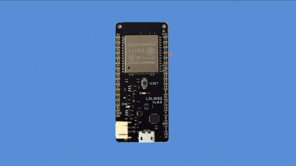
WeMos Lolin32 ESP-WROOM-32 IoT application development platform with Bluetooth/WiFi transmitter on the ESP32 wireless communication controller.
 The basic idea behind microcontroller development today is to minimize chip size while increasing the number of integrated components contained within a single structure. However, having achieved significant success with the ESP8266 chip,
Espressif Systems did not stop there. Keeping up with the times and in a small miracle, Espressif launched a powerful and flexible new solution combining the popular wireless standards of WiFi and Bluetooth, found in nearly every electronic device today, with a truly comprehensive innovation, expanding the ESP32 family of products for a variety of low power designs from hobbyists to industry professionals.
ESP32 series controllers are suitable for a wide range of unique applications: connectors for Internet of Things (IoT) computing concepts, tools for collecting and storing data, sensors of all kinds, audio or video streaming, add-ons for advanced electronic products, speech or image recognition mechanisms. It also finds applications in home automation, controlling lighting, power outlets, or door locks. In addition, ESP32 can participate in developing coordination and interaction circuits of industrial equipment or monitoring systems for electronic tags (beacons), educational, industrial, and service robotics, children’s toys, and any compact portable smart devices.
WeMos Lolin32 Specifications
- Model: Wemos Lolin32 v1.0.0
- Power: 5 V / 3.7 V external battery
- Working Voltage: 3.3 V
- Current Consumption: Up to 500mA
- Controller: ESP-WROOM-32, low-power, dual-core ESP32-D0WDQ6 processor based on 32-bit Xtensa LX6
- Clock speed: up to 240 MHz
- Internal memory:
– 448 Kbytes of ROM for loading and basic functions
– 520 Kbytes of static RAM for data and instructions
– 8 Kbytes of fast static RAM for the real-time power supply domain (RTC), accessible via the main CPU during boot from deep sleep mode
– 8 Kbytes of slow, static RAM for the real-time power domain (RTC), accessible through the co-processor during Deep Sleep mode boot
– 1 Kbit eFuse, 256 bits occupied by the system (MAC address and chip settings), 768 bits for user applications, including flash encryption and chip ID - Built-in memory
– 32MBit / 4MBit ROM, 40MHz - Radio Frequency Range: 2.4GHz-2.5GHz (2412M-2484M)
- WiFi:
– Client, Access Point, Client+Access Point (station, softAP, station+softAP)
– WiFi protocols: 802.11 b/g/n, up to 150 Mbps
– Output power in 802.11b mode: +20.5 dBm
– WiFi MAC support
– STBC 2×1 technology
– Antenna: PCB, wired onboard - Bluetooth:
– Version 4.2 BR/EDR and BLE specifications
– Transmit power: +12dBm
– NZIF receiver with -97dBm sensitivity
– Adaptive Frequency Hopping (AFH)
– Class-1, class-2, and class-3 transmitter without external power amplifier
– Supports multi-communication in both classic BT and BLE modes
– Support for Piconect and Scatternet multilink connections
– Support for CVSD and SBC voice codecs - Encryption: WAPI, WEP, TKIP, AES, SHA-2, RSA, ECC
- General purpose outputs (input/output, GPIO): 26
- Analog inputs (ADC): 12, 12-bit
- Analog outputs (DAC): 2, 8-bit
- Maximum current per general purpose contact: 12 mA, 6 mA recommended
- Interfaces: GPIO, UART, I2C, I2S, SPI, PWM, Touch, Ethernet MAC, SDcard, SDIO, IrDA
- UART baud rate: up to 5MBit/s
- Built-in Tx/Tx switch, HF matching transformer, power amplifier
- Built-in blocks: Mains matching, phase-locked, power management, regulation blocks
- Built-in: Hall sensor, capacitive touch sensor
- Supports Arduino, NodeMCU, MicroPhyton, ESP-IDF
- Support for SPIFFS, FATFS file systems
- SDK support, UART/OTA firmware upgrade
- Programmable GPIO5 output LED
- Autonomous power supply:
– External battery charge controller: LTC4054
– Charging current: 500mA
– Charge mode indicator
– Compatible Batteries: Lithium Polymer (Li-pol), Lithium Ion (Li-ion)
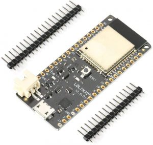
– Connector: PH-2, 2.0 mm - Pin spacing: 2.54 mm
- Dimensions: 58 x 25.4 x 7.7 mm
- Weight: 5.8g
Autonomous Power, Battery Charging, an Indication
WeMos Lolin32 platform includes a set of hardware combining the primary set of hardware needed to create a nearly complete and independent IoT device, working from a stationary or autonomous power supply in the form of a rechargeable lithium battery of any shape and size. In addition to the ESP-WROOM-32 chip and all minimal circuitry, the board scheme has a prudent controller LTC4054. It monitors and adjusts voltage levels of a single battery element, preinstalled in the project’s design. The main reason for installing the emergency backup power supply mechanism is to ensure continuous and stable operation of the ESP32 chip in case of a possible short or extended power failure on the main DC power supply, which would lead to some unfavorable and sometimes even undesirable consequences.
The LTC4054 chip monitors the current battery voltage in standalone or emergency power modes. A charged lithium battery pack delivers 3.8 volts to its terminals. Inactive modes of the Wemos Lolin32 ESP-WROOM-32 platform, the battery voltage smoothly decreases, and the more the load on the board, the faster the discharge occurs. If it reaches 2.9 volts, the power transfer to the board circuitry stops until recharged again. The LTC4054 chip generates a low charge current of 500mA at 4.2 volts, enough to charge a single lithium battery with a rated capacity of 2200-3000mA.
A built-in blue LED indicator connected to the LTC4054 controller shows the current state of charge of the battery. Its constant glow indicates that the battery is in recharge mode. When the battery charge cycle is complete (or the battery is physically absent), the LED goes off completely. Peculiarities of the LTC4054 controller functioning cause occurring short flashes of the LED.
First Power-Up, USB Port
Everything you need for a quick start with the Wemos Lolin32 module is already present on the board itself. Communication between the PC and the Lolin32 platform is implemented on the Silabs CP2104 interface converter chip, installed on the board and linking the central ESP-WROOM-32 controller and the built-in USB port. Thus, all the user has to do is connect the PC and board with the usual wire with USB A – Micro-USB B connectors. Suppose the devices with a similar CP2104 chip have not been connected before. In that case, the Windows operating system will ask for the appropriate driver to be installed.
First of all, the USB port is intended to control the module. It allows you to add your applications to the ESP32 controller or download proprietary software (firmware). Otherwise, the USB port is only used to power the board.
Real-Time RTC Power Domain, ESP32 Power Save Modes
The ESP32 chip is prepared by Espressif Systems developers for several operating modes, depending on the features of the product being designed and how it is powered. For example, with a reliable external source of constant, stable voltage, the controller can operate fully in active mode. On the other hand, the battery’s autonomous or emergency power supply forces us to think about the maximum and efficient energy-saving directly related to the duration of the Wemos Lolin32 platform. For such purposes, the ESP32 chip houses an ultra-low power co-processor (ULP processor) and provides the following modes:
- Active mode – The radio transmitter units are constantly on. The chip can transmit and receive data or conduct continuous radio surveillance. Current consumption is 95-240 mA.
- Hibernate modem mode – all features of the ESP32 chip are functional, except for WiFi and Bluetooth radio transmitter blocks. In addition, the processor frequency is automatically adjusted depending on the load of the core and the peripherals used. As a result, current consumption is reduced to 20-68 mA.
- Light Sleep Mode – The ESP32 processor is halted, while the RTC real-time power domain memory and peripherals, as well as the ULP processor, are operational. Sleep mode exit is based on wake-up events (MAC, host, RTC timer, or external interrupts). The operating current in the light sleep mode does not exceed 0.8 mA.
- Deep Sleep Mode – Only the memory and peripherals (RTC_GPIO, RTC_I2C) of the RTC real-time power domain, including the ULP processor, receive voltage. All other ESP32 elements are de-energized. The WiFi and Bluetooth connection settings are stored in the RTC memory. As a result, power consumption is reduced to 10-150 µA.
- Hibernation mode – The built-in 8 MHz crystal oscillator, ULP processor, and RTC domain memory are de-energized. The RTC timer and some RTC GPIO pins remain active, which can return from hibernation mode. The operating current in a hibernation mode is only 5 µA.
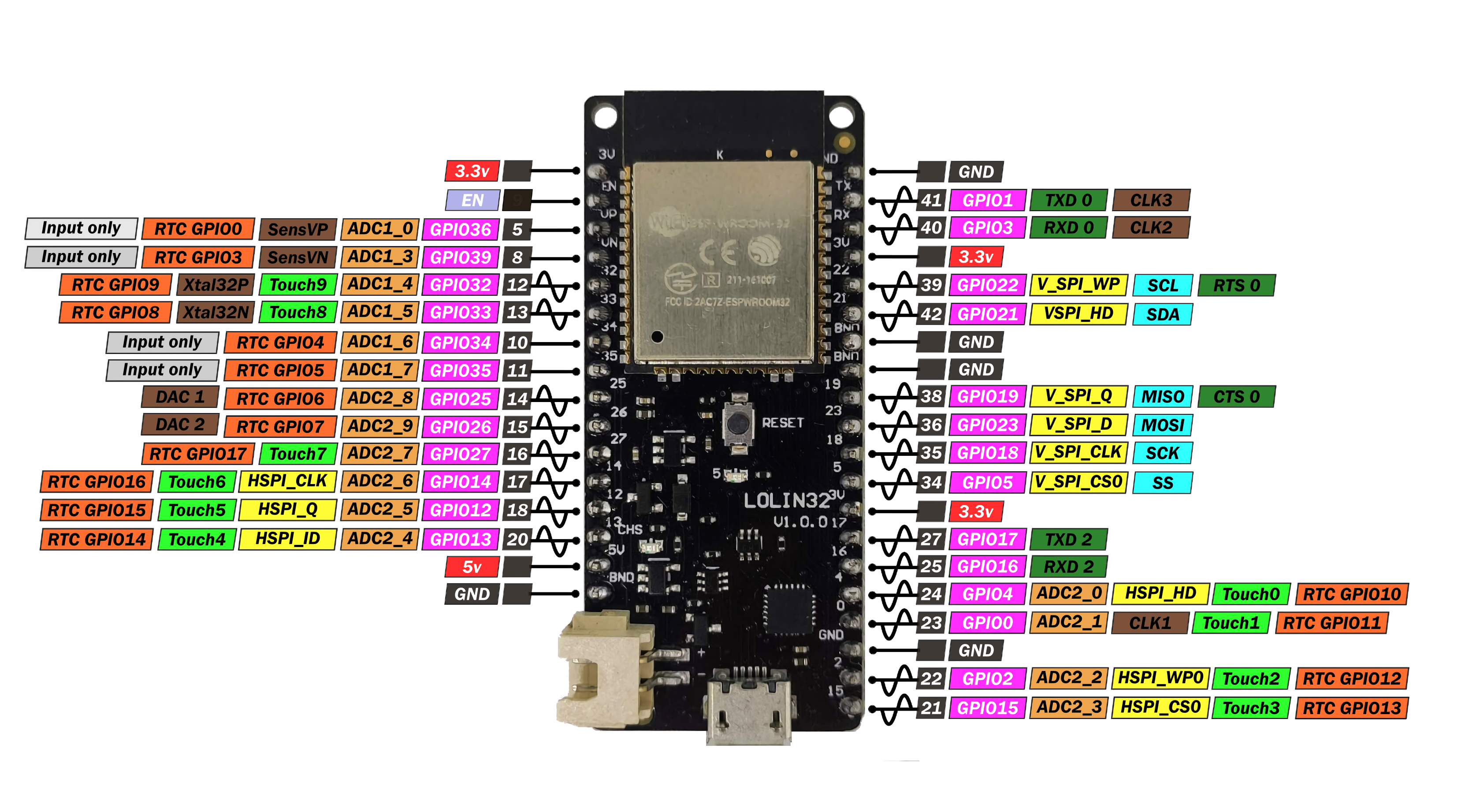
WeMos Lolin32 Pinout, ESP-WROOM-32 ESP32 Pinout
Digital data reception and transmission between the controller and peripherals connected to the board’s general-purpose pins (GPIO) is based on 3.3-volt logic. The input/output voltage of the digital output in the range of +2.64…+3.6 volts is commonly referred to as a high-level signal or logical unit. Voltages in the range of -0.3…+0.33 volts are called low-level signals or logical zero. Many ESP-WROOM-32 pins have built-in controlled resistors that set the contact logic signal level to plus (pull-up) or minus (pull-down). Most of the board pins can be smoothed with various interfaces (UART, I2C, I2S, PWM, HSPI, VSPI, EMAC service channel, and others). The recommended current for a single GPIO pin is 6 milliamps, with a current limit of 12 milliamps.
- VCC 3V3 – 3.3-volt platform operating voltage pin, designed to power external peripherals.
- CHIP_EN – ESP32 operating mode contact can also be used to restart the WROOM-32 controller (Reset).
- GPIO0…39 – general purpose pin, data input/output. Reassignable to compatible functions. The output is defined by GPIO numbering (e.g., GPIO1 = 1). A low-level signal on the GPIO0 pin puts the ESP32 in software update mode.
- RTC_GPIO0…17 is the digital pin of the RTC real-time power domain. Incoming signals from peripherals connected to the RTC_GPIO pins wake up the ESP32 from light sleep mode. Requires pre-programming.
- Sens_VP(positive), Sens_VN(negative) – contact of internal Hall sensor connected to internal ADC signal amplifier1. Excludes the use of the Hall sensor in conjunction with other functions that distort measurements of the surrounding magnetic field.
- XTAL_32KP(positive), XTAL_32KN(positive) – external quartz oscillator contact at 32.768 kHz.
- VDET1, VDET2 – analog contact of real-time power domain RTC. Similar to digital pins, designed to bring ESP32 processor out of power-saving modes. Requires pre-program preparation.
- VCC 5V – contact to supply Wemos Lolin32 with the stabilized voltage of 5 volts.
- GND – general, ground.
Avoid exceeding the maximum current of 12 milliamps and the voltage of more than 3.3 volts on the GPIO pins, damaging the ESP32 microcontroller.
Special Functions and Interfaces
- A0…A19 – analog-to-digital converter (ADC1, ADC2). Allowed input voltage 0-3.3 V, conversion range between 0-4095, 12-bit. Under the condition of active WiFi communication, the ADC2 pins cannot be used as analog pins.
- DAC1, DAC2 – digital-to-analog converter (DAC1, DAC2). The outputs generated on the board’s pins the outgoing analog voltage, set on the software level by the values of variables ranging from 0 to 255. The digit capacity is 8-bit.
- UART – asynchronous serial bus interface, which includes the main data receiving line RX, TX, as well as service lines of the request to send data RTS and permission to send data
- CTS. Of the 3 existing UART interfaces in ESP32, only UART0 and UART2 are available. The user can reassign each line to any GPIO.
By default, the Arduino IDE predefines one UART0 bus with pins GPIO1 (TX) and GPIO3 (RX). - I2C/IIC is a bidirectional serial interface consisting of the SDA data and SCL clock lines. Allows one to several parallel-connected external sensors, sensors, displays, etc., to be switched on the same bus in master or peripheral modes. Each device must have a unique address to be addressed. The ESP32 has 2 I2C hardware interfaces, reassigned by the user to any GPIO.
By default, the Arduino IDE provides one I2C bus with pins GPIO22 (SCL) and GPIO21 (SDA). - SPI is a serial peripheral interface (HSPI, VSPI) bus configurable to connect external devices in master and slave modes. Each bus consists of main lines: data transfer from master to slave MOSI and from slave to master MISO, clocking CLK, and peripheral selection CS0. In addition, the SPI includes QUADWP and QUADHD service pins.
- I2S – Electrical bus interface used to switch digital stereo audio devices with a serial bus and cameras and displays with a parallel bus. It is used for collecting, processing, and transmitting audio data or for receiving/transmitting the information. The ESP-WROOM-32 contains two I2S protocol buses, each bus line (DATA, BCK, WS, SYNC, ENABLE) can be reassigned by the user to any GPIO. In addition, the I2S0 and I2S1 timing lines are allocated to pins designated CLK_OUT1-3.
- Touch0…9 – contact of the capacitive sensor. Responds to a change in capacitance in the electrical output circuit caused by a person or object touching the corresponding contact. It can serve as a source of waking up the ESP-WROOM-32 from power-saving sleep modes.
- SD/SDIO/MMC – host interface (HS2) supporting SD V3.01 memory cards.
- SDIO/SPI – peripheral interface (SD) that supports industrial SDIO 2.0 memory cards.
- PWM – Pulse Width Modulation (PWM) – Digital pulse width modulation of a signal-controlled at the software level. Any GPIO pin present in the WROOM-32 supports PWM.
- Ethernet MAC (EMAC) – IEEE-802.3-2008 compliant Medium Access Control (MAC) MII/RMII interfaces. To connect to a physical LAN bus (twisted pair, fiber, etc.), the ESP32 processor requires an external PHY physical interface device. The PHY is connected via a 17-signal MII interface or a 9-signal RMII interface.
The built-in SPI flash memory of 4 MB of the ESP-WROOM-32 controller is hardware bound to 6 hidden pins (GPIO6-GPIO11), whose pins are not on the Wemos Lolin32 board. Therefore, it is not recommended to use these pins or reassign them to other functions.
Programming in the Arduino IDE
Before you start writing and flashing sketches to the ESP32 Wemos Lolin32 platform, you should add its compatibility with the Arduino IDE environment. To do this, follow all the steps described in the chapter “Adding the ESP32 platform to the Arduino IDE”.
By default, powering up the Lolin ESP-WROOM-32 controller starts the execution mode of the program code previously written to the internal memory. The new sketch is flashed by putting the ESP32 controller into the programming mode by shorting the GPIO0 and GND pins (or by holding down the pre-soldered button to these pins) during the whole process until it is completed.
When programming the module, the internal algorithm of the Arduino IDE editor simultaneously flashes its ESP32 software with each new sketch, thus removing the previous versions of the firmware from the corresponding memory area.
The following simple example makes the programmable LED, combined with the GPIO5 pin, blink.
void setup() {
  // initialize the LED_BUILTIN pin (GPIO5) into the output mode
  pinMode(LED_BUILTIN, OUTPUT);
}

void loop() {
  // lighting up the LED with the low-level signal LOW
  digitalWrite(LED_BUILTIN, LOW);
  // wait a second
  delay(1000);
  // turn off the LED with a high HIGH
  digitalWrite(LED_BUILTIN, HIGH);
  delay(1000);
}
Some of the digital GPIO pins in the ESP32 chip are only for receiving data from the peripherals. An example of a sketch that monitors the state of the GPIO36 pin and sends values to the serial port.
// Define the pin
int INPUTpin = 36;
//Set a variable to store the signal level, 0 - low, 1 - high
int VAL = 0;

// Prepare
void setup() {
  // initialize the input pin
  pinMode(INPUTpin, INPUT);
  // Open the serial port at 115200 bps.
  Serial.begin(115200);
}

// main loop
void loop() {
  // Read the value at the GPIO pin input
  VAL = digitalRead(INPUTpin);
  // Output the information to the serial port
  Serial.println(VAL);
  // wait a second
  delay(1000);
}
Wemos Lolin32 Firmware Update on Software with AT Command Prompt
The Espressif Systems team, for their ESP32 chips and their variants, release firmware with a built-in AT command interpreter based on the open-source software development kits (SDK) ESP-IDF. The user can compile their custom firmware, adding or removing support for features needed in the project. The way the WROOM-32 processor is controlled in such firmware is significantly different. The firmware code contains predefined scripted commands that perform various actions on the ESP-WROOMR-32 controller settings. For example, AT commands allow to establishment and break of WiFi or Bluetooth BLE connections, send and receive data, work with the file system (in the original firmware, the function is disabled) or change the UART bus parameters. Any AT command is sent to Wemos Lolin32 through the peripheral serial interface UART (GPIO16, GPIO17) from the master device and always begins with the abbreviation AT. The main bus UART0 in Lolin32 is used exclusively for programming the processor. The list of supported AT commands is published in the “Technical information” section.
All actual firmware archives for ESP-WROOM-32 with AT command prompt are freely accessible on the manufacturer’s official site. The firmware includes several binary files (.bin), the purpose of which is clear by their names. The addresses of the memory locations for each partition are written in the download.config text file. The developer of the ESP32 controller proposes to update the software using the universal, off-the-shelf Flash Download Tools program.
Before writing a new software version, it is highly recommended to delete all previously stored information and partition table from the WROOM-32 flash memory (ERASE button). This procedure helps to avoid possible subsequent startup errors of the ESP32 controller. Unfortunately, both are clearing the memory, and updating the software means that the ESP32 controller has to be put into programming mode beforehand.
In the Arduino IDE application development environment, to access the AT commands, you must connect an optional USB-to-TTL converter to the PC’s USB port and correctly connect the RX, TX, and GND pins of both boards. Then change the COM port of the compatible board to the one assigned to the CP210x USB-TTL adapter in the editor settings and open the serial port monitor at 115200 baud. Finally, the functionality of the firmware is checked by sending a simple “AT” command, which returns an “OK” response to the window.
Video Guide: Wemos Lolin32 OLED and Gpio
Final Words
WeMos Lolin32 is an excellent board for beginners. It is affordable, easy to use, and has much potential for development. If you are starting out in the world of Arduino or are looking for an affordable board to begin with, the WeMos Lolin32 is a great option.
Regarding your description of the LTC4054 section of the board it seems to indicate that battery power to the WEMOS board is disabled if there is no USB power and battery voltage drops below 2.9V.
“If it reaches 2.9 volts, the power transfer to the board circuitry stops until recharged again.”
From what I can tell the battery will continue to supply power to the WEMOS board below 2.9V. Hopefully I’m missing something. It is true that the LTC4054 chip itself will go to a low power mode below 2.9V battery voltage but three is a separate VBAT connection to the rest of the WEMOS board that will continue to supply power. Is there something in the ESP32 that turns it off below 2.9V? Doesn’t look like the LDO regulator will. Is it assumed that the battery has low voltage cutoff protection built in?
I’m trying to understand this aspect of this board for an application I have.
Thanks,
David.
Hello, David! Absolutely, it has a low-voltage cutoff protection.
It being the battery or the WEMOS LOLIN32 board? Can you explain where the low voltage cutoff circuit is?
Thanks,
David
Hello
First of all wonderful writeup on the LOLIN32. It was really helpful to me.
I do have a question that was not made to clear. When powered by the USB the 5v pin next to the battery connector seems to output 5 Volts, but when I plug in a battery that 5V pin is at 0Volts. Is this normal is that 5V pin an input power or output power for the LOLIN32?
Hello, Glenn! Yes, in most cases, this is normal