A multimeter is a versatile tool that can be used to measure voltage, current, and resistance. It is important to know how to read the symbols on a multimeter in order to properly use the tool. The symbols on a multimeter are relatively easy to understand once you know what they represent. The following article will explain the meaning of the most common symbols found on a multimeter.
Warning. This article describes a standard multimeter with the most common functions. Depending on the model of the multimeter, its functionality may be greater and include additional features. Only those that are available in almost every device are described here, as well as the deciphering of the designations on the multimeter.
Let’s briefly describe the main components of the device:
- Electronic display
- Scale of notations
- Switch
- Button “ON/OFF” (there is a special position for the regulator instead)
- Stylus sockets
- Special connectors for testing transistors (present on some testers)
- Test indicator (buzzer and red LED)
- Battery
Of all the above the most important point is the scale, because if you set the wrong regulator you can burn the measured radio component or the device itself. Therefore, the deciphering of the designations on the multimeter is a very important point when working with this device.
Symbols on the Multimeter
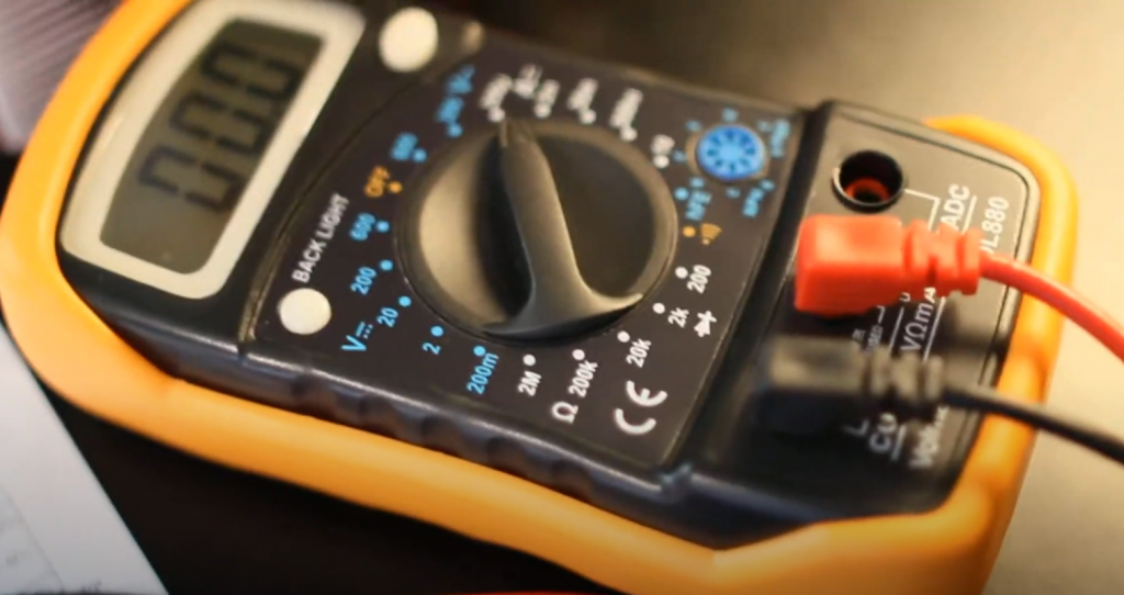
The scale designation includes a circular position switch, as well as symbols indicating certain parameters, divided into sectors.
Each sector is responsible for measuring one specific parameter (e.g. resistance). Within a sector there are several regulator positions, each position represents a measurement value. Each sector is marked with a special symbol. All sections are separated from each other by lines.
Where Do I Connect the Multimeter Probes?
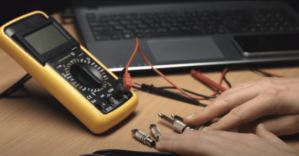
The probes for the multimeter are included in the kit. One probe is red and the other is black. The housing of the probe is made of dielectric material, and there is a sharpened metal rod at the end.
Attention! Remember the golden rule: red is always a plus and black always a minus. It is therefore important not to mix up the connection sockets, otherwise there is a risk of confusion. Always connect the red probe to the plus side and the black probe to the minus side.
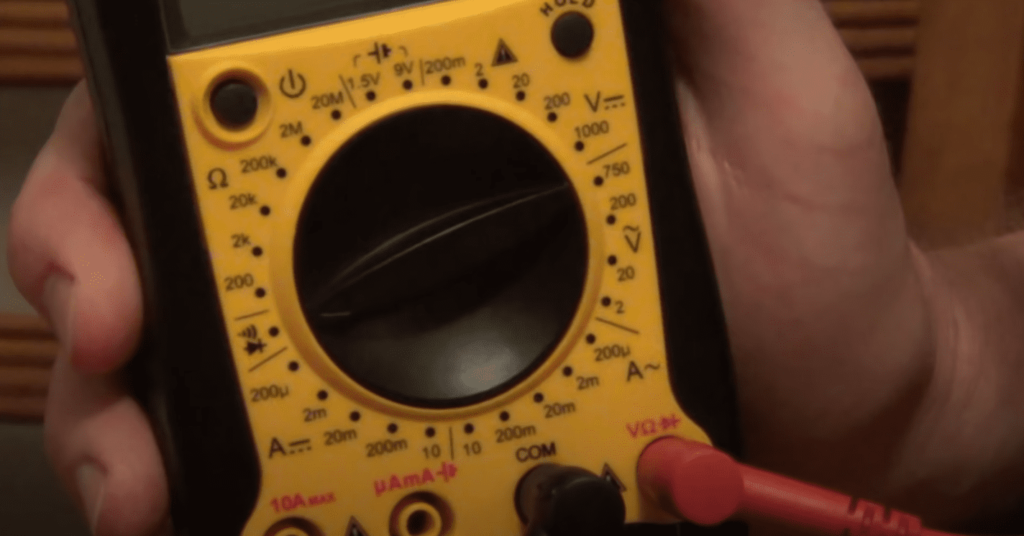
The probes are connected to special sockets, which are also marked. There can be three or four sockets, depending on the model of the multimeter.
The sockets for connecting the probes:
- COM socket – denotes the minus (mass, common). The black colored probe is plugged into it. Everyone knows that when you measure the AC voltage, say, in a socket, the polarity does not matter. Nevertheless, follow the following rule: if there is a certain wire (probe) and there is a special hole for it, you must connect this wire exactly to this hole, because the black color of the wire unambiguously hints to us that it is the minus one.
- VΩCX+ socket is the plus and the red wire is connected to it. This socket is used for measuring resistance, voltage, frequency, temperature, checking diodes and transistors. Simply put, this jack is used in all measurements except current measurement.
- The 20A socket is a special socket. A red stylus is connected to it, and the function of this socket is to measure current up to 20 amperes. 20 amps is a very high amperage, so be careful. Again, a very important rule: When measuring current, the tool (in our case, a multimeter) must be connected in series and only in this way. If you see “UNFUSED” next to this socket, keep in mind that the measurement is done without using a fuse, so try not to burn the device. You also need to know how the DC current is labeled on the multimeter.
- The MACX socket is the socket for measuring small micro and milliampere currents. If the inscription “0.2A MAX FUSED” appears next to it, it means that the measurement is made with the fuse protection of the device, the maximum measurement value is 0.2 ampere.
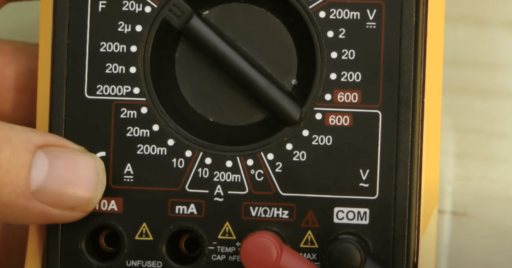
A red triangle labeled “MAX 600V” may be drawn on the meter (values may vary depending on the multimeter model). This is the maximum voltage measurement value. Do not measure voltages above this setting.
Warning! If you do not know the limits of the measured value – set the regulator to the maximum value, as you measure – move to the lower side. For example, we know that the measured device (for example, battery) has constant voltage, but we do not know the approximate range (either 24 volts, or 12 volts, or maybe 1.6 volts). In this case, set the regulator to the maximum value of the DC voltage measuring sector and move to the lower side.
Very important: Never touch the metal part of the probe with your fingers when taking any measurements, especially when measuring dangerous voltages or currents.
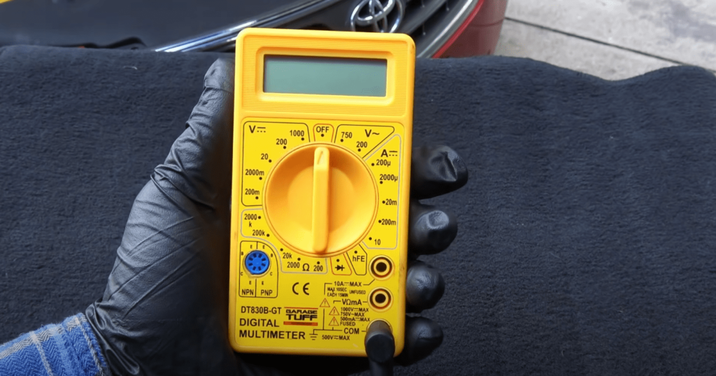
Multimeter Switch Ranges
First let’s touch on the subject of turning the multimeter on and off. Usually there is an “ON/OFF” button, but some models of multimeters have a special sector with the same name. There are also testers that turn off on their own, after some time.
The same regulator, or switch – as one prefers, it is possible to turn it clockwise or counterclockwise. To measure any parameter, just move the regulator to the desired sector at the desired value.
Important: Sectors are marked with letters, and ranges are marked with digits.
Deciphering of designations on the multimeter, which you need to remember once and for all:
- DCV – DCV measurement sector
- ACV – AC voltage measurement sector
- DCA – DC measurement sector
- ACA – alternating current measurement sector
How Is the Resistance Marked on the Multimeter?
From high school physics we remember that resistance is measured in ohms, in honor of the German physicist Georg Simon Ohm. The designation on a multimeter is “Ω”, and the resistance ratings on a standard meter are as follows: 20 Ohm, 200 Ohm, 2 kOhm, 20 kOhm, 200 kOhm, 2 Mohm, 20 Mohm, 200 Mohm. Depending on the model of multimeter used, the value range may be different.
The measurement of this parameter is very popular in both electronics and electrical engineering. With the help of resistance you can very quickly check the performance of a light bulb, coil, wire, etc.
To measure the resistance, move the knob to the “Ω” sector and select the desired value.
DC Voltage Markings on Multimeters
Voltage is measured in Volts, after the Italian physicist Alessandro Volta. We have already written above that the DC voltage measurement sector is indicated by the abbreviation “DCV”. But, many models use the symbol “V-” instead of this abbreviation. In this abbreviation, the letter “V” stands for voltage and the symbol “-” for DC.
Also, to avoid confusing the DC voltage sector with the AC voltage sector, remember the following: the range of the DC voltage sector is wider than the range of the AC voltage sector.
To measure the DC voltage, set the regulator to the desired value in the “V-” sector.
Attention! If during the measurement you mixed up the poles, the display will show the same value, but with a “-” sign. There is nothing wrong with this.
AC Voltage Markings on Multimeters
AC voltage is also measured in Volts. The abbreviation “ACV”, or, as in the previous case, the abbreviation “V~” is the designation on the multimeter, the decoding is “v” – voltage, the sign “~” – AC.
For an electrician, this parameter is the main concern, because outlets, switches, etc. always use AC voltage. Our mains are 220 volts and the multimeter has values of 700V (750V) and 200V.
When measuring AC voltage, the polarity does not matter. That is, it makes no difference which socket you plug the red or black probe into when measuring the voltage at the socket.
How Is the DC Current Indicated on the Multimeter?
Current is measured in Amperes, after the French physicist Henri Ampere. On the multimeter the DC measurement sector is designated as DCA, or simply DC. The controller, as in the previous cases, is set to the desired value for the measurement in the DC sector.
Do not forget that the device is connected in series to measure the current. What does this mean? To measure the amperage, we break the circuit.
For example, we need to measure the amperage in a phase wire. You can’t just touch the wire in two places with the stylus. There must be a break in the wire (or circuit), and it is into this break that we connect the device.
How Is the AC Current Indicated on the Multimeter?
Not every tester is capable of measuring AC current, but on some models this function is present. To answer the question “how AC current is indicated on the multimeter”, the AC current sector is indicated as “A~”, similar to AC voltage.
Generally speaking, a multimeter is not well suited for measuring alternating current. It is better to use a clamp meter for this purpose.
What Is the hFE Sector on a Multimeter?
Some multimeter owners may see a hFE sector on their meter, and in addition to it, two jacks with four connectors each. This sector is responsible for testing transistors (measuring the current transfer ratio). The sockets are signed “NPN” and “PNP” and the connectors are signed “E”, “B”, “C”.
There are two types of transistors: “PNP junction” transistor and “NPN junction” transistor. The letters “E”, “B”, “C” stand for “emitter”, “base”, “collector” respectively.
To check the transistor, set the regulator to the hFE sector, look at the pinout of its legs, the type of transistor, then plug the transistor itself into the right socket. If your transistor is defective, the instrument will show a value of “0”. Of course, many novice electricians are frightened by the abbreviation hFE, but that is why you need a deciphering of the designations on the multimeter, so that all the incomprehensible becomes clear.
Diodes Test on a Multimeter
It was mentioned above that almost every multimeter has a special LED and a buzzer. In addition, there should be a sector on the measurement scale with a diode drawn on it. This is all necessary to check the diodes for proper operation, as well as to check the continuity of circuits and everything else, with a resistance of not more than 50 ohms.
To test a diode, you need to remember its properties. A diode passes current only in one direction. We set the regulator to the diode icon and start checking by reversing the poles. A good diode in one position will show 1 on the display, the LED will light up and the buzzer will beep. When the poles are reversed, the multimeter will show a diode value, e.g. 436 millivolts. A faulty diode – will test both ways.
These are only superficial principles of the diode, but this is enough to check if the diode is working properly with a multimeter.
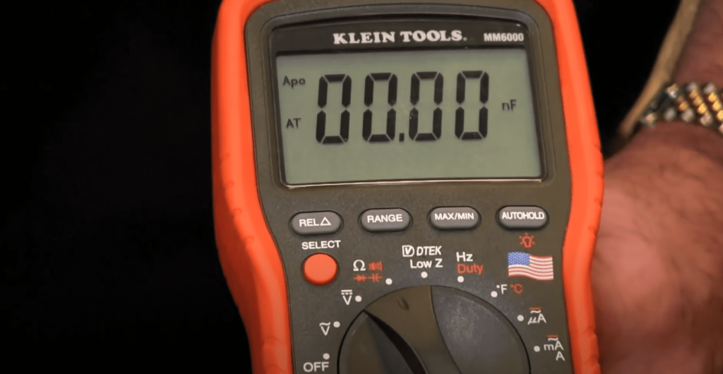
Checking Capacitance of Capacitors With a Multimeter
To measure the capacitance of a capacitor you must set the switch to the F (Farad) range. To check the capacitance of a capacitor the multimeter must have this function. To make the measurement the -CX+ sockets are used. The “-” and “+” stand for the polarity of the connection.
The capacitance measurement range of this multimeter ranges from 200 microfarads to 20 nanofarads.
FAQ
What does kHz on a multimeter mean?
This parameter is not present on all devices. “Hz” – frequency unit (Hertz). With this sector you can measure the frequency of the signal.
This button is also not present on all devices, its full name is “Data hold”. It serves to fix the received data on the display. The desired value will be displayed exactly until you press this button again. Someone considers it useless, someone periodically uses it.
What is DC on a multimeter?
DC is the direct current that flows in a circuit. A multimeter is used to measure this current.
What do the letters HV on the multimeter mean?
This means “HIGH VOLTAGE”. If you see this designation, it means that the device is switched to a high voltage measurement mode. You should be extremely careful when taking such measurements.
Are Fluke multimeters good?
Fluke multimeters are some of the best in the business. They’re known for their accuracy and durability, and they’re used by professionals all over the world. If you’re looking for a high-quality multimeter, Fluke is a great option.
Budget vs. expensive multimeter, which is better?
There is no simple answer to this question. It depends on what you need the multimeter for and how much you are willing to spend. If you only need a basic multimeter for simple tasks, then a budget model will probably suffice. However, if you need a more advanced multimeter with more features, then you will need to spend more money on a more expensive model.
Can you tune an amp with a multimeter?
Yes, you can tune an amp with a multimeter. You’ll need to set the multimeter to the correct setting and measure the voltage at the amp’s output terminals.
Can you test a transformer with a multimeter?
Yes, you can test a transformer with a multimeter. You will need to measure the voltage across the transformer’s primary and secondary winding. If the transformer is working properly, you should see a voltage difference between the two windings.
Can you test a capacitor with a multimeter?
Yes, you can test a capacitor with a multimeter. To do so, you first need to discharge the capacitor. Once the capacitor is discharged, you can measure the capacitance with a multimeter.
Multimeter or battery tester, which is better?
Both multimeters and battery testers can be useful tools, depending on what you need to test. If you need to test for voltage, current, or resistance, a multimeter would be the better choice. If you just need to test the health of a battery, a battery tester would be sufficient.
Clamp meter or multimeter, which is better?
Both clamp meters and multimeters are good tools to have in your toolkit. Each has its own strengths and weaknesses, so it really depends on what you need to use it for. If you need to measure electrical current, a clamp meter is the better choice. If you need to measure voltage, resistance, or other electrical properties, a multimeter is the better choice.
Related Video: Multimeter Symbols – What Do They Mean?
Summing Up
Understanding multimeter symbols is vital to using a multimeter correctly. Without knowing the meaning of the different symbols, it would be easy to make a mistake while taking measurements. Always consult the user manual for your specific model of multimeter before taking any measurements.