
A multimeter is a must-have tool in the hands of any electronic engineer. They are used to determine the electrical characteristics of a circuit; they can be used to measure voltage, current, capacitance, resistance, determine breaks, and test semiconductor elements’ performance. Such devices are used both by professional electricians and beginners. In this article we will talk about how to use a multimeter, we can say that it is a beginner’s manual.
How You Can Use a Multimeter
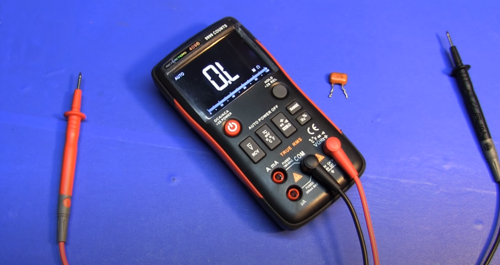
A multimeter is a professional tool used to measure electronic components’ characteristics, check the voltage and current, and find short circuits. They are used in industry, electrical engineering, and repair work. Nowadays, digital multitesters are mostly used, and we will start with them.
With a multitester, you can measure a battery or battery from a phone, determine the polarity of an LED, and measure the socket’s current and voltage. The multimeter has several operating modes that are activated to test a particular parameter.
Multimeter Operation
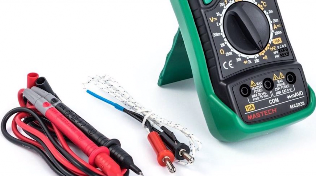
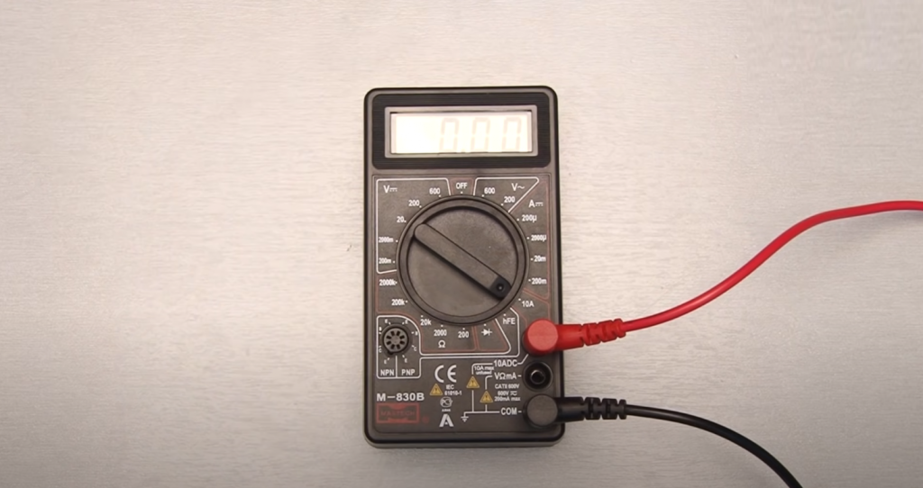
The most common version of the device interface can be considered on the example of the model DT-830. It is a rectangular housing with a display and a knob that switches modes. It also comes with two probes – red and black, with which the measurement is made. They are connected to the desired component. The measured value is displayed on the screen.
The switch positions are divided into blocks. These include:
- On/Off device switch;
- Voltmeter for DCV measurement (measures from 200 millivolt to 1000 V);
- ACV voltmeter (measures 100 to 750 V);
- DCA ammeter (ranges – 0 to 200 mA, 2000 mA, 0 to 20 mA, 200 mA;
- ammeter section for measuring large direct currents 10 A;
- measurement of hFe transistors (there are special connectors with letters E – emitter, B – base, C – collector to connect transistors);
- diode check unit;
- ohm resistance test (0 to 200, 2000 ohms, 0 to 20, 200 or 2000 kOhms).
Later models have temperature sensing and audible wire-checking of the circuit.
Power
Power is supplied by a battery. You can judge the quality of the assembly by the power connector. In a reliable and quality device, the battery connection is made through connectors for crowns. Cheap multimeters are equipped with conventional springs.
There are several connectors for connecting the probes. Choosing the right one depends on the value being tested. If you connect the wires incorrectly, the tester can burn out. The black probe is inserted into the COM (common) connector, the red one into the other desired output. If necessary, the probes can be replaced with better ones.
Multimeters are classified according to the accuracy of the measurement. The simplest devices are those with 2.5 digits – they give an accuracy of 10%. Currently, the most used are multimeters with a measurement accuracy of 1%.
How a Multimeter Works
At the heart of any digital multitester is an analog-to-digital converter. When an input signal is received, it is converted into a reference signal.
In order to measure electrical parameters, the tester must be connected to the circuit or the element to be measured. The connection is made by means of wires. On the ends of the probes are plugs that are placed in the socket of the multimeter. The other end is needed to make contact with the electronic circuit.
DC current is measured when connected in parallel to the circuit, and voltage is measured when connected in series. The resistance is measured with the circuit de-energized.
The multimeter should be operated according to the following algorithm:
- turn on the device;
- select the desired type of measurement with the help of the knob or the appropriate button;
- set the measurement range;
- connect the probes;
- press the ends of the probes against the circuit or component;
- take readings from the screen.
When the work is finished, the tester should be turned off, and the probes should be removed from it.
Types of Multimeters
There are two main types of multimeters – digital and analog.
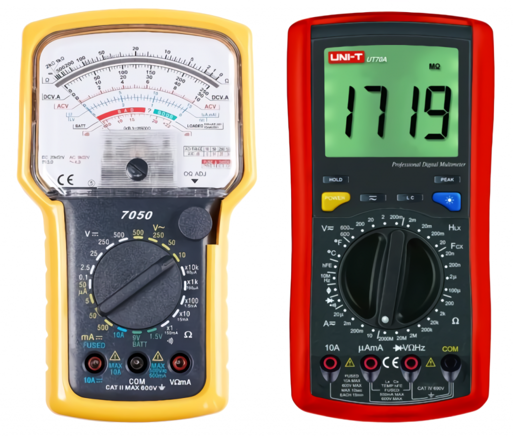
Analog devices are the older models. They have a scale with an arrow. Readings are determined by this arrow, which is the main disadvantage of such a measuring device. The arrow is not fixed in one place, so there will be an error in the measurement. It is also necessary to monitor the position of the probes. The main advantage of arrow devices is visibility. When the arrow moves, you can see what changes occur to the signal.
Digital or electronic measuring devices are the most popular instruments. They have practically superseded analog multimeters. The measurement result is displayed on the screen as numbers. The digital tester is simple and easy to use, it has extended functionality, and its affordable price makes it even more relevant.
It is important to note that an analog and digital device’s principle of operation is the same.
Digital oscilloscopes refer to professional testers. They have a graphical display that shows the readout characteristics over time. Both analog and digital devices can be equipped with an oscilloscope. You can read how to use an oscilloscope here.
There are models of multimeters that work automatically. In them, you only need to set the type of measurement, the boundary of the device sets itself. There are also multitesters connected with a computer. With their help, the characteristics are measured, and the data obtained are sent to a computer for later analysis and use.
An inexpensive mid-priced device is excellent for home use. They provide accurate readings of 1%. Cheap and high-quality devices include DT-830, 831, and others from this line. The last figure determines the novelty of the modification. The new devices expand the functionality.
Professional equipment has its features. Multimeters can be equipped with a water-proof case to work in conditions of high humidity. Also, the housing can be protected from mechanical influences and vibrations. There is a function for recording measurements, which may be required for further analysis of measures and graphing. Modern devices can communicate not only with a computer but also with a tablet or smartphone via Bluetooth. Professional multimeters are more expensive, so they are used by specialists in special conditions.
How to Use a Multimeter to Measure Current
Measuring current may be necessary in the following cases:
- clarifying the power consumption of a household appliance;
- evaluation of the load connected to the network;
- searching for a defect in an appliance;
- checking the level of charge on the battery or battery pack;
- to look for current leakage.
Operation of the multimeter in the ammeter mode is one of the most difficult and dangerous. The difficulty lies in finding a break. If the circuit has a terminal or other collapsible mechanism, there is no problem. But if you need to measure a household electrical appliance, you will either have to cut the wire or devise a fixture to take measurements. Also, you will have to move the red probe to a different hole in ammeter mode when you change the upper limit.
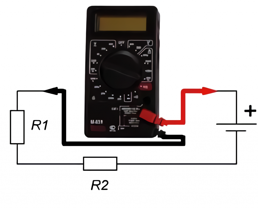
A multimeter that measures amperage must be plugged into an open circuit. This kind of connection is called a series connection. The current flows through the tester, and the value is displayed on the screen.
It is essential to set the measurement range on the multimeter correctly before measuring. An incorrectly chosen upper limit can cause the device to break down. If there is no information about the possible current strength, it is advisable to set the highest limit. For the DT-830, the red probe should be placed in the 10 Amp socket. The switch knob should also be at the 10 Amp mark.
In some cases, the reading may be lower than 0.2 A, which means that the limit is set too high. If the limit is too high, the red probe can be placed in the middle slot. The adjustment is then made with the switch knob. The limit is decreased bit by bit.
Since the multimeter in ammeter mode is plugged into a circuit and becomes part of it, safety precautions must be observed when working with the power grid. Even small currents can lead to irreversible consequences for humans.
The current should be measured as quickly as possible. Otherwise, the tester may burn out. The marking on the multimeter itself informs about this. The recommended measuring time, the interval between the measurements, and a fuse’s presence are also recorded.
Important: You cannot measure the amperage in a socket outlet. Only the voltage between the zero and the phase contact is there. A short circuit will occur when you plug the stylus into the socket.
It is not often that a multimeter is plugged into a household appliance. Usually, it is turned on to check the correct organization of the home network and check the real power of appliances. In this case, multitester is included at the point of circuit breakage – to the neutral or phase wire of the device’s power cable. After the circuit is assembled, the cable must be plugged in, and the household appliance must be activated. After a few seconds, the current strength in amperes will appear on the screen. The problem is connecting to a household appliance is creating a breakpoint. Cutting the wire is not the best option. It is possible to create a special fixture that allows the measurement, but it makes the process more complicated.
How to Use a Multimeter to Measure Voltage
A multimeter can measure DC and AC voltage. The knob is turned to the appropriate position to do this. Then the measurement range is selected. It is better to know it in advance. It is easier than with current – for example, the voltage in the socket is 220 V + error, and on batteries and batteries, the value is written. Based on these values, the closest limit is chosen. If the limit is chosen too high, you can gradually decrease its value. This is indicated by the number 1 on display.
Then the probes are connected. Red – to the socket marked VmA, the probe from it to the plus on the circuit or the element. Black – to the socket marked COM, on the circuit, or the device to the minus.
The probes should be attached to the device to be measured. The screen will show the voltage in the measured area. If the probes are mixed up, the value will be negative.
The probes remain in the same position to measure alternating voltage. The switch should be moved to the ACV sector. Then the measurement limit is selected. There is no polarity in AC measurement so that the probes can be connected to any contact.
It is best to choose a range of 600 to 750 volts to measure the socket voltage.
How to Use a Multimeter to Measure Resistance
The probes remain in the same position. The switch should be switched to the ohm Ω department. The free ends are applied to the element to be measured. You also need to set the limits – if this value is unknown, the switch is set to the maximum scale.
Then the multimeter is tested – you need to connect the two probes to each other. If the function works properly, zero will be shown on the screen.
Here you can also check the resistance of the coil of unknown rating. In this case, it is not necessary to set the maximum limit. The device will not be damaged. The probes should be connected to the coil. If the display shows zeros, the limit should be decreased by one position. The test is done again, and if necessary, the limit is decreased. This procedure is done until a number appears on display. This value will be the nominal resistance of the component.
The red probe is set to V/Ω to test diodes, transistors. To test a diode, connect the black probe to the cathode (minus) and the red probe to the anode. The resistance value of the diode will appear on the ohmmeter. If you confuse the connection of the probes, a 1 will appear on the screen. If 1 appears in both cases – the diode is burned out.
The transistor is tested in hfe mode. The device’s ends are respectively plugged into outputs B, E, C, which correspond to the base, emitter, and collector. When the transistor is inserted, the instrument will display the amplification values of the transistor.
Rules for Making Measurements
Any work related to the power grid and electricity must be carried out observing safety rules. The following requirements should be adhered to:
- Work carefully, carefully, and always check that the probes are correctly turned on and the mode selected.
- Never grasp probe with both hands. When dialing with voltage, if an insulation breakdown occurs, the electric current will pass through the human body and the heart’s most dangerous area. Therefore, it is better to use one hand to place the first probe and then the second. In this case, the risks are reduced.
- Measurement of unknown values begins with setting the maximum limit. Then, as necessary, the value is decreased by the discharge. It is also important not to forget that the red dipstick will also have to be moved to another socket in the ammeter mode.
- It is important to remember that all multimeters are different, and each model may have its own peculiarities of operation. Therefore, you should carefully read the instruction manual before starting measurements.
- It is necessary to be careful when taking measurements. It is necessary to give time to discharge the circuit elements because the residual charge may be enough to get an electric shock or break the tester.
- It is necessary to observe the correct connection of the multimeter in this or that mode. The ammeter should be connected in series, i.e., become part of the circuit. The voltmeter is connected in parallel. For resistance measurement, an external power supply is not required. A measure of resistance under voltage is prohibited!
- The measurement should be carried out as fast as possible. If necessary, the result is recorded with the hold button. Long measuring times result in fast discharging of the power supply and heating of the circuit components.
Observance of the rules is mandatory for a correct measurement procedure.
FAQ
What does AC mean in electrical terms?
AC stands for alternating current. It is a type of electrical energy that alternates between positive and negative charges.
Are Fluke multimeters good?
Fluke is a company that manufactures electronic measuring instruments, and it has been doing this for more than 40 years now. It has a reputation for being one of the most reliable and accurate manufacturers of these products in the world. Fluke multimeters are the best in the market. They are reliable, accurate, and well-built.
What is the symbol for continuity on a multimeter?
A continuity test is a simple way to determine if a circuit has electricity flowing through it. A multimeter can perform this test by pressing the continuity button and then touching the probe tips on two points in the circuit. If electricity is present, you will hear a beep or see the light on the multimeter.
The symbol for continuity on a multimeter is the wave or diode symbol.
Which is better: a multimeter or a capacitor tester?
A multimeter is better than a capacitor tester because it can measure voltage, current and resistance.
Conclusion
This is the end of my tutorial. We hope that our material has helped you to learn how to use the basic modes of the universal device, and now you know how to use a multimeter at home and what you need to measure resistance, voltage, and current in the circuit!


I had never used a multimeter before I started my job as an Electrician’s Assistant. My boss showed me how to use one and it has become one of my most essential tools. If you have never used a multimeter before, here is a quick guide on how to use one.
To use a multimeter, you first need to select the correct setting. For example, if you want to measure AC voltage, you would select the “ACV” setting. Once you have selected the correct setting, you then need to attach the probes to the correct terminals. The black probe is typically attached to the “COM” or common terminal, while the red probe is attached to the “VΩmA” or voltage/resistance/current terminal.
It’s good to know that the most popular type is a digital multimeter. My brother was at my house a couple of weeks ago helping me build new furniture, and he talked about how he needs to get multimeters for his company within the next couple of months. I’ll pass this information along to him so he can know how to pick the right ones for his job.