
A multimeter is an electrical measuring device with various functions. It can be used to check voltage, current strength, as well, as the derivatives of these values – resistance and capacitance. You can also use the multimeter to check the performance of various electronic components. In this article, we will learn how to test a capacitor and its capacitance with a multimeter.
Condenser and Capacitance
Capacitors are used in almost all chips and are a frequent cause of its inoperability. So in case of failure of the device, it is necessary to check this element first.
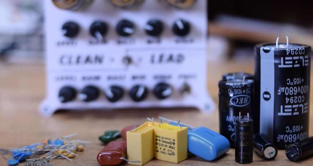
Types of capacitors by dielectric type:
- vacuum capacitors;
- with gaseous dielectric;
- with inorganic dielectric;
- organic dielectric;
- electrolytic capacitors;
- solid state.
Main capacitor faults:
- Electric breakdown. It is usually caused by exceeding the permissible voltage.
- Breakage. It is related to mechanical damage, shaking, vibration. The cause may be poor design and operating conditions.
- Excessive leakage. The resistance between the covers varies, resulting in a low capacitance of the capacitor, which cannot retain its charge.
All these causes cause the capacitor to become unusable for further use.
Before Testing the Capacitor
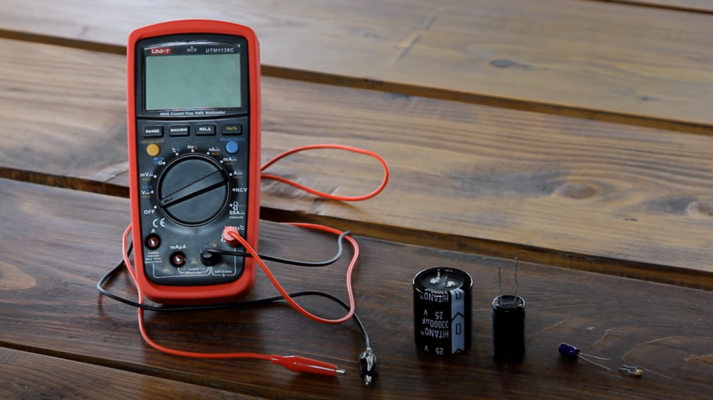
Since capacitors accumulate electrical charge, they must be discharged before checking. This can be done with a screwdriver – you need to touch the leads with a sting to create a spark. You can then call out the component. You can check the capacitor with a multi-tester or with bulbs and wires. The first method is more reliable and gives more accurate information about the electronic element.
You should inspect the capacitor before starting the test. If it has cracks, broken insulation, leaks, or bloating, the internal electrolyte is damaged, and the device is broken. It should be replaced with a working device. If there are no external damages, you will need to use a multimeter.
Before making the measurements, you need to determine whether the capacitor is polar or non-polar. The polarity of the first condenser must be respected; otherwise, the device will fail. In the second case, it is not necessary to determine the positive and negative outputs, but the measurements will be made using a different technology.
You can determine the polarity by the mark on the body. There should be a black stripe on the part with zero markings. There is a negative contact on the side of this foot, and on the opposite foot, there is a positive contact.
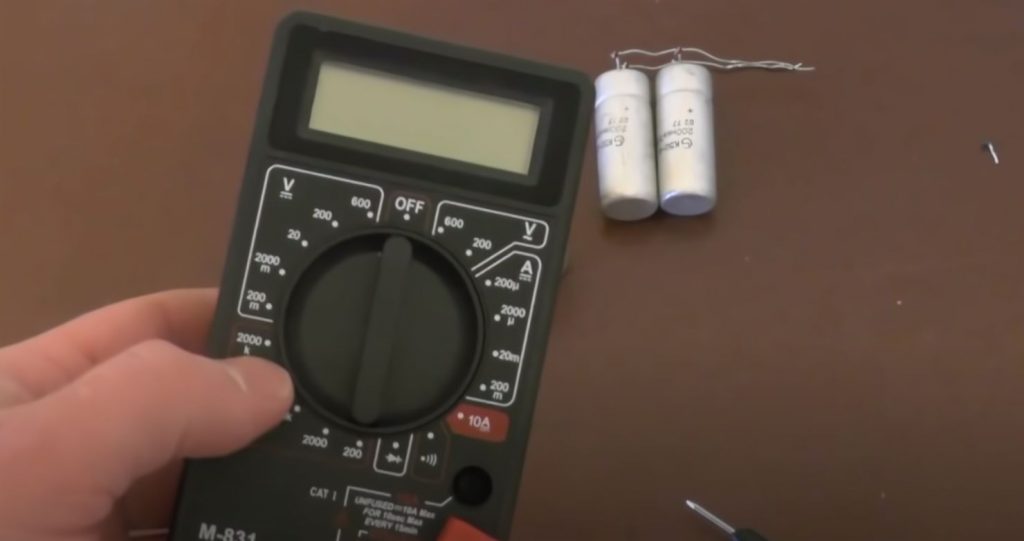
Measuring the Capacitance in Resistance Mode
The multimeter switch should be set to resistance mode (ohmmeter). You can see if there is an open circuit or a short circuit inside the capacitor in this mode. To check the non-polar capacitor, the measurement range is set to 2 MOhm. For the polar product, a resistance of 200 ohms is set because at 2 MOhm, and the charging will be fast.
The capacitor itself must be unsold from the circuit and placed on a table. Probes of the multimeter to touch the capacitor terminals, observing the polarity. In non-polar parts, to observe the pros and cons is not necessary.
When the styli touch the legs, the display will show the value, which will increase. This is due to the fact that the multi-tester will charge the component. After a while, the value on the screen will reach one, which means that the device is functional. If the test immediately lights up 1, there is a break inside the device, and it should be replaced. A zero value on the display indicates that a short circuit has occurred inside the capacitor.
If a non-polar capacitor is being tested, the value should be higher than 2. Otherwise, the unit is not operational.
The above-described algorithm is suitable for the digital tester. When using an analog device, the check is even easier – you only need to observe the arrow stroke. The probes are connected in the same way, the mode – resistance check. The smooth movement of the arrow indicates that the capacitor is correct. The minimum and maximum value at connection speak about the breakage of the electronic part.
It is important to note that the check-in ohmmeter mode is made for parts with a capacity above 0.25 μF. For smaller ratings, special LC meters or high-resolution testers are used.
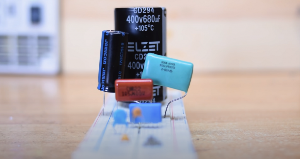
Condenser Capacitance Measurement
The capacitor is the main feature of the capacitor. It is indicated on the device’s outer shell, and if there is a tester, you can measure the real value and compare it with the nominal value.
The switch of the multimeter is converted into a measuring range. The value is set equal to or close to the nominal value indicated on the component. The capacitor itself is installed in special holes -CX+ (if they are on the multimeter) or with the help of probes. Styli are connected in the same way as when measuring in resistance mode.
When connecting the probes, the resistance value should appear on the monitor. If it is close to the nominal characteristic, the capacitor is correct. When the difference between the obtained and the nominal values is more than 20%, the device is punctured and must be changed.
Measuring the Capacitance Through Voltage
A voltmeter can also be used to check the performance of a part. The value on the monitor is compared to the nominal value, and from this, a conclusion is made about the device’s serviceability. To check, you need a power supply with a lower voltage than the capacitor.
Keeping the polarity, you need to connect the probes to the leads for a few seconds to charge. Then, the multimeter is switched to voltmeter mode, and performance is checked. A value similar to the nominal value should appear on the display of the tester. Otherwise, the device is broken.
Other Ways of Testing
You can check the capacitor without unsoldering it from the chip. To do this, you need to connect a capacitor with the same capacity in parallel. If the device will work, the problem is in the first element, and it should be changed. This method can only be used in low voltage circuits!
Sometimes they check the capacitor for sparks. You need to charge it and use a metal tool with an insulated handle to close the leads. There should be a bright spark with a characteristic sound. At low discharge, you can conclude that it is time to change the part. This measurement must be made with rubber gloves. This method is used to check high-capacity capacitors, including starting capacitors, which are designed for voltages above 200 volts.
It is undesirable to use test methods without special devices. They are not safe – the slightest indiscretion can cause an electrical shock. Also, the objectivity of the picture will be disturbed – the exact values will not be obtained.
Difficulties of Testing
The main difficulty in determining the performance of the multimeter capacitor is it’s unsoldering from the circuit. If the component is left on the board, the measurement will be affected by other circuit elements. They will distort the readings.
There are special Undervoltage testers on the probes that allow checking the capacitor directly on the board. Low voltage minimizes the risk of damage to other circuit elements.
Comparison of Capacitor Testing Methods with a Multimeter
Testing capacitors is an essential skill for electronics enthusiasts and professionals. Using a multimeter, you can determine whether a capacitor is functioning correctly or if it needs replacement. This table provides a comparison of different testing methods with a multimeter to help you identify the most suitable approach for your needs.
| Testing Method | Procedure | Advantages | Disadvantages |
|---|---|---|---|
| 1. Resistance Test |
|
|
|
| 2. Voltage Test |
|
|
|
| 3. Capacitance Test |
|
|
|
| 4. ESR Test |
|
|
|
In this table, we compare four different methods for testing capacitors with a multimeter. Each method has its advantages and disadvantages, making them suitable for different scenarios. The resistance test is a quick method but only helps identify shorted capacitors. The voltage test is useful for identifying leaky capacitors but requires a known voltage source. The capacitance test directly measures the capacitance value but cannot detect leakage or high ESR. The ESR test is effective in identifying high Equivalent Series Resistance but cannot detect open capacitors. Depending on the situation, you can choose the most appropriate testing method to ensure the proper functioning of your capacitors.
FAQ
Which is better to test capacitors: budget multimeter or capacitor tester?
There is no right answer to this question. It depends on the type of capacitor that you are testing. For example, if you are testing a capacitor for a digital circuit, then it would be best to use a budget multimeter because it will provide more accurate readings than the capacitor tester. If you are testing a capacitor for an analog circuit, then it would be best to use the capacitor tester because it provides more accuracy and convenience.
When conducting these tests, the most important thing is that you be aware of your test equipment capabilities and know what type of capacitors you are testing.
Are Fluke multimeters good for capacitors testing?
The short answer is yes. But, before you purchase a Fluke multimeter for capacitors testing, there are some things to consider.
Fluke multimeters are one of the most popular brands of electronic test equipment used in the electronics industry. They provide accurate and reliable measurements in various applications, including electrical measurement and testing, mechanical measurement and testing, and manufacturing inspection.
How do I know if a capacitor is bad?
It’s pretty easy to tell if your capacitor is bad: If the voltage across the terminals of your capacitor drops below 0V or the current increases significantly, then that’s a sign that it might be on its way out.
How to Test Capacitance – Useful Video on Youtube
Excellent video describing the process of testing capacitors.
Final Words
Now you know how to test a capacitor with a multimeter. You can use this knowledge to troubleshoot or repair your own electronics. Thanks for reading!


