
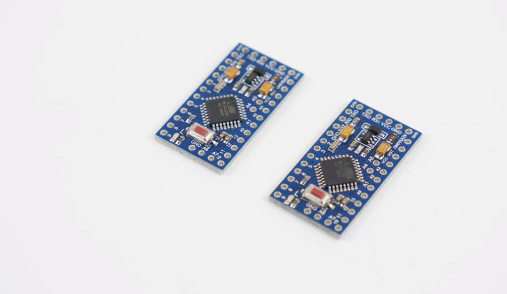
Arduino Pro Mini controller is the smallest and cheapest device in the line. The board is comparable in size to a flash drive. The basis of the controller is ATmega168 with a frequency of 8 MHz or 16 MHz. Arduino is used for installation in small projects. The platform is compatible with most sensors and modules for the Arduino.
Description of the Board
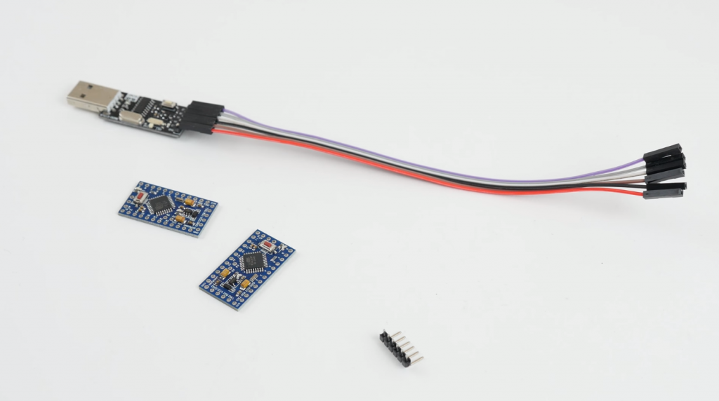
The properties of the Arduino Pro Mini are similar to those of the Arduino Uno and Nano boards. Their difference is the inability to flash the Pro Mini via USB-UART. Instead, an FTDI converter interface wire or an optional Sparkfun board is used to create a connection to the computer. There are also differences in the speed at which the chip operates. The Arduino Pro Mini has a slower speed than the Arduino Uno, but this has almost no effect on projects.
Working with the Arduino Pro Mini needs to be done carefully. If the user burns the chip by applying an excessive voltage to it, it will be impossible to remove and replace it.
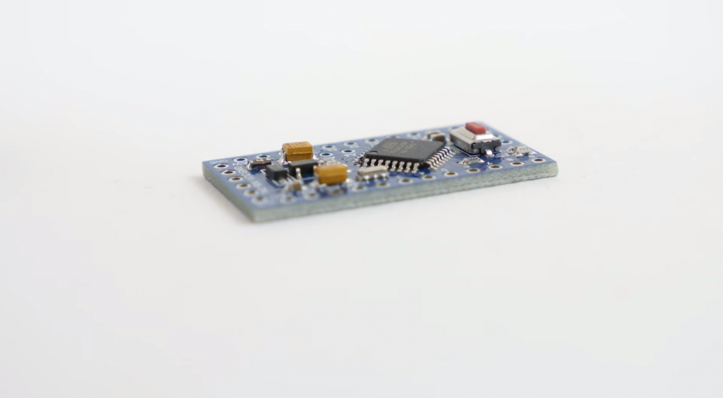
The connectors are not soldered to the platform. Wiring can be done either through connectors or by hinged mounting. The legs can be soldered.
There are two models of the Arduino Pro Mini microcontroller – 3.3V and 5V. The first one uses a clock frequency of 8 MHz. The second one runs at 16 MHz. Which model it is should be indicated on the case.
Traditionally, you write the sketch to the microcontroller via the Arduino IDE. You will need special adapters to download the code. It is initially sold with the firmware already installed.
Specifications of the Arduino Pro Mini microcontroller:
- Operating voltage of 3.3V and 5V (depending on the model);
- 14 pins, 6 of which are used as PWM pins;
- Direct current for input and output 40 mA;
- The total current of the pins – not more than 200 mA;
- 16Kb of flash memory, 2Kb are used for the boot loader;
- 1 KB of RAM;
- 512 bytes of EEPROM;
- Clock frequency – 8 MHz or 16 MHz depending on model;
- I2c interface;
- The dimensions of the board are 0,70 x 1.29 inches (18 x 33 mm).
Power can be supplied in three ways:
- Through an FTDI adapter;
- By feeding a stabilized voltage to the Vcc pin;
- By feeding voltage to the RAW pin.
What projects can be implemented based on the Arduino Pro Mini:
- Controllable designs for quadcopter;
- Timer;
- Device for soil moisture analysis;
- Automatic watering of plants;
- Device for measuring precipitation and wind speed;
- Aquarium automation.
And many other projects for home and country houses.
Arduino Pro Mini Pinout and Circuit Diagram
The circuit diagram of the Arduino board is shown below.
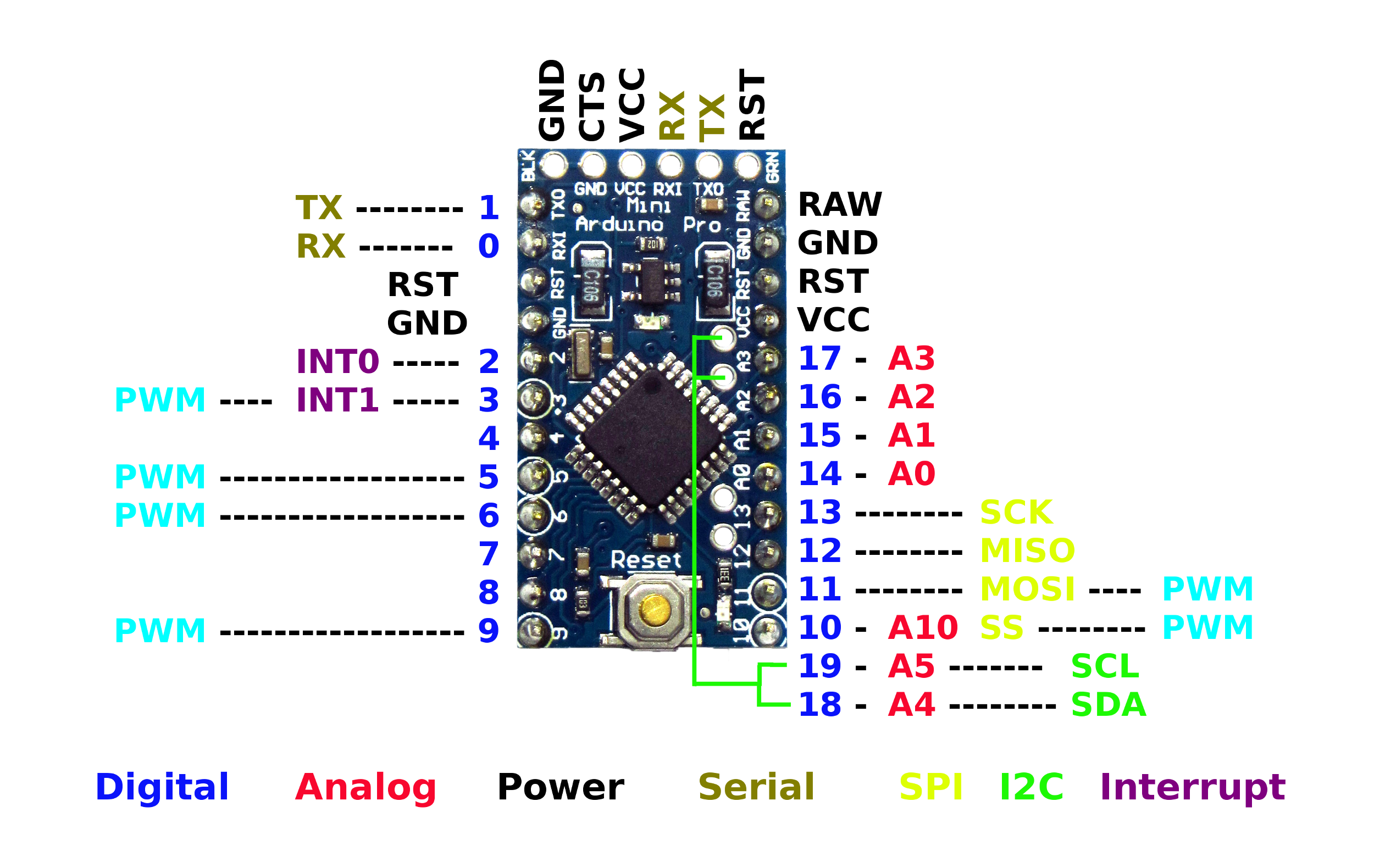
The microcontroller has 14 pins, each of which can be configured as an input or output. The pins are labeled with a digital number. The analog pins are labeled A. The operating voltage is 3.3V or 5V.
Pin assignment:
- Serial Bus – 0 and 1 (RX, TX). Intended for receiving and transmitting data.
- External interrupts – 2 and 3 can be used for interrupt triggering.
- PWM pins – 3, 5, 6, 9, 10, 11.
- SPI – 10 (SS), 11 (MOSI), 12 (MISO), 13 (SCK).
- LED indicator – 13.
The six analog pins have a resolution of 10 bits. Some pins have additional functionality:
- I2C – A4 (SDA), A5 (SCL).
The board is also equipped with an additional Reset pin. At the low level, it resets the microcontroller.
Flashing Arduino Pro Mini
The miniature size of the board does not allow you to flash it without external help. There are several ways of pouring the sketch into the microcontroller:
- Through a USB to TTL adapter;
- Via Arduino Uno;
- Via SPI interface using an Arduino board with a connector to connect to a computer.
The simplest method is the first one.
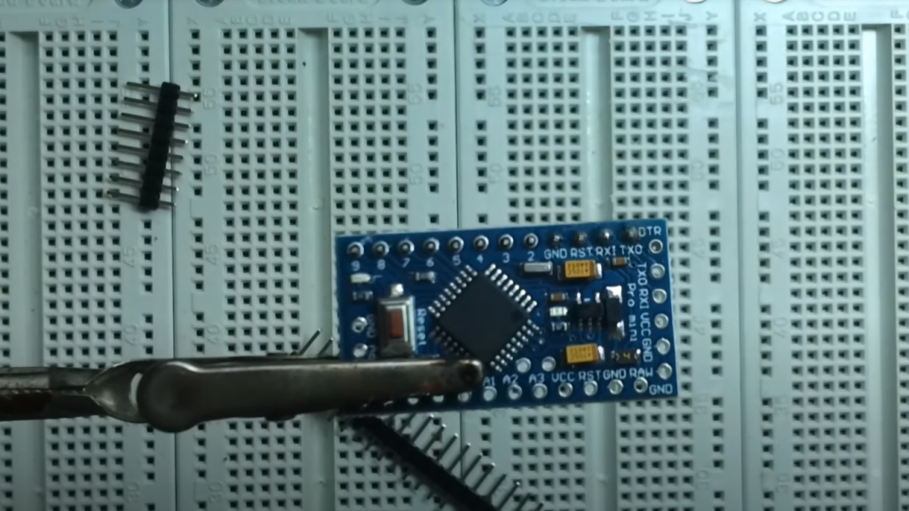
Flashing with a USB to TTL Adapter
A special adapter, a UART adapter, can be found on the market. There are many kinds of such adapters, and the cost of each product is low. We advise buying adapters with RST or DTR pins as they simplify the flashing process.
To flash the adapter, you need to connect to the Arduino: you need to connect the ground from one and the other device, Vcc – to +5V or +3.3V (depending on the model), RX – TX, TX – RX. Then you have to connect the construction to the computer, install the driver and start the firmware. The computer will detect which port the board is connected to. The driver can be downloaded from the official website. The downloaded archive must be unpacked and installed.
Then you have to run the Arduino IDE, select the right board and port number, and load the firmware. This is done as follows:
- Click “Load”;
- Then the compilation will start – you will see the inscription “Compiling a sketch”;
- After the inscription “Upload,” you must press the Reset button on the board (in adapters with RST or DTR, you don’t need to press the button).
The sketch will be loaded into the microcontroller. You can see the successful end of the procedure by the blinking LED.
Flashing with the Arduino Uno
You will need a classic Arduino Uno board in a DIP case for flashing. On this board, you will need a special plug from which you can carefully remove the microcontroller. It is important to do everything carefully so that you don’t bend the legs of the processor.
With the wires, you need to connect the Arduino Pro Mini to the connector. Here is how to connect the pins: RX-RX, TX-TX, GND-GND, 5V-VCC, RST-RST.
After the connection, you can start the standard loading of the sketch through the Arduino IDE.
Flashing via SPI Interface
This method is the most inconvenient and time-consuming. Flashing the board is done in 2 steps:
- Flashing the Arduino Uno microcontroller as an ISP programmer;
- Setting up the development environment and loading the code into the Arduino Pro Mini.
Algorithm of the first step:
- Launching the Arduino IDE;
- Opening “File” – “Examples” – “11. ArduinoISP” – “ArduinoISP”;
- Next “Tools” – “Board” – “Arduino uno”;
- “Tools” – “Port”, and select the desired COM port number;
- Next, you need to compile and load the code into the Arduino Uno.
Then the two boards need to be connected with conductors according to the above diagram: 5V – VCC, GND – GND, MOSI (11) – MOSI (11), MISO (12) – MISO (12), SCK (13) – SCK (13).
Now you have to configure the Arduino IDE for the Arduino Pro Mini. This is done as follows:
- “Tools” – “Board” – select the desired Arduino Pro Mini board;
- In the same menu, select “Processor” – select the appropriate processor with the desired clock frequency;
- Then you have to set the port to which the board is connected;
- “Tools” – “Programmer” – Arduino as ISP;
- Then you have to load the sketch through the programmer.
It is important to note that the code’s loading must be done through the special menu “load via programmer”. Here you can get confused, that’s why this way is not convenient. Downloading in the usual way will cause the code to fill in the Arduino Uno. If you want to learn how to program Arduino Pro Mini, check this guide.
Once you have booted the microcontroller through the adapter, you can no longer flash the microcontroller. You have to fill in a new bootloader through “write bootloader”.
If you have problems with any kind of firmware loading, you should check the board’s connection.
Programming Using Arduino Pro Mini
The standard Arduino IDE development environment is used. Once the device is connected to the computer, you need to select the board in the list correctly. The main thing is not to mix up the 3.3V Arduino and the 5V Arduino. Which one is used must be written on the case.
The Serial Port item is used to select the correct port to which the board is connected. Then you can load a program to the board by pressing the Upload button.
The loading may take a long time, and you may get an error. To avoid it, you need to press the reset button while loading the sketch when the message Binary sketch size: xxx bytes appears. During the loading process, the LEDs on the board will light up. After filling the sketch you have to disconnect the microcontroller and apply voltage to it.
A Comparison of the Characteristics of the Different Arduino Boards
The main characteristic in which the Arduino pro mini differs from the other boards is the dimensions. The dimensions of the Arduino Pro Mini are only 0,70 x 1.29 inches (1.8 cm x 3.3 cm). The Arduino Nano board is a bit longer at 0.74 x 1.69 inches (1.9 cm x 4.3 cm). The Arduino Uno board is about two times bigger. Its dimensions are 2.71 x 2.08 inches (6.9 x 5.3 cm). The Arduino Mega has the largest dimensions – 4.01 x 2.12 inches (10.2 x 5.4 cm).
The number of pins is also different. Arduino Pro Mini, like Arduino Nano and Arduino Uno, has 14 digital pins. Arduino Mega has 54 digital inputs/outputs, of which 15 support PWM.
The important difference between Arduino Pro Mini and the other boards is the absence of USB-UART firmware. The other microcontrollers can be flashed this way, except the Arduino Nano. This is flashed with an rt232 converter.


The top row of holes in the image of the Arduino Pro Mini in the ‘ARDUINO PRO MINI PRINTOUT AND CIRCUIT DIAGRAM’ section are labeled GND, CTS, VCC, RX, TX, and RST from left to right, but the holes on the board itself are marked BLK, GND, VCC, RXI, TXD, and GRN. This may be a silly question, but why are they different?
The manufacturer considered this marking to be more successful
Hi Robert. Thank you for your prompt reply, but I guess a better question would have been ‘which is correct?’. VCC, RX, RX and GRN/RST match, but what about GND/BLK and CTS/GND? The labels for GND and CTS are confusing me about which is CTS and which is ground.
Steve
If your Pro Mini won’t program try selecting Mini in the IDE instead. Some low cost ProMini boards are actually Minis.
The standard FTDI pinout matches those pins. CTS is not used and can be connected to GND. The pin labelled RST *should* be labelled RTS (request to send, the serial handshaking signal that pairs with CTS, clear to send). It is NOT a reset pin. Some FTDI adaptors bring DTR to this pin. It is used to reset the ATMega at the start of programming by pulling the ATMega reset pin down through a capacitor on the board.