
This article will talk about nRF24L01, one of the most popular and inexpensive radio modules for Arduino and IoT projects. The nRF24L01 modules for Arduino are easy to find in any online store and relatively inexpensive. At the same time, with their help, it is possible to organize quite reliable multi-channel communication with packet delivery confirmation between Arduino controllers and other devices. This article will look at the description, the pinout of nRF24L01, and what libraries can be used with this radio module.
Description of the nRF24L01 Wireless Module
You cannot create a really interesting project without creating communication between the different parts of the system. This is why it is so important to choose the right platform for communication between the modules. The NRF24l01 is perfectly suited to create distributed systems with sensors and controllers separated by up to 328 ft.
The nRF24l01 is a highly integrated 2Mbit/sec low power (ULP) chip for the 2.4 GHz band. Multiple devices can be interconnected to transmit data over the radio link. Up to seven devices can be interconnected to form a common 2.4 GHz radio network, with one module acting as master and the others as slaves. In addition, the NRF24l01 radio module is cheap, so that it can be found in a wide variety of projects, from smart homes to various homemade robots.
nRF24L01 Specifications
- Low power consumption;
- Advanced ShockBurst hardware protocol gas pedal;
- ISM operating system;
- Data transfer rates of 250 kbps, 1 Mbps, and 2 Mbps;
- Fully compatible with all standard nRF24L Nordic series as well as nRF24E and nRF240 series;
- 3.3V supply voltage;
- Operating temperatures from -40F to 185F, storage temperatures from -40F to 257F;
- The range of communication up to 328 ft.
The module is based on nRF24L01+ manufactured by Nordic Semiconductor. All necessary elements and a connector plug are located on the chip. The SPI interface can be used to configure the protocol, set the output power, and establish data exchange channels.
Scope of the nRF24L01 Module
One of the most important components of IoT projects is communication. nrf24l01 can be successfully applied in the following areas:
- Mobile electronics;
- Computers;
- Automated systems;
- Various elements of the smart home – alarms, temperature control, and other functions;
- Games;
- Consumer Electronics.
The nRF24L01+ board includes a frequency synthesizer, demodulator, amplifiers, and other components. The channel number determines the operating frequency of the module. The frequency range in which communication takes place is 2.4 – 2.483 GHz. Channels are located every 1 MHz. That is, zero corresponds to a frequency of 2.4 GHz, channel 83 – 2.483 GHz.
The module has 4 operating modes – Power Down, Standby, RX mode, TX Mode. RX mode current consumption is higher than TX mode.
The Enhanced ShockBurst protocol is responsible for stable and reliable data transmission and reception. The receiving device must give a response to data reception, thus confirming the feedback.
nRF24L01 Pinout
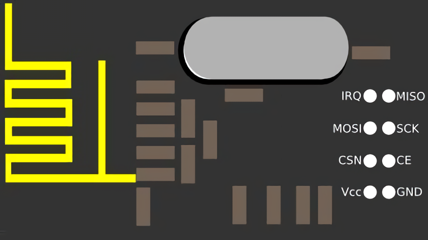
In addition to the power outputs, the signal lines can be connected to contacts with a supply voltage of 5 V. The device’s input, which is connected to the board, must consume a current not exceeding 10 mA.
The chip contains the following outputs:
- GND – ground;
- VCC – supply voltage 3.3V;
- CE – high level of the chip;
- CSN – switching on the low level of the chip. In this case, the device responds to SPI commands;
- SCK – SPI clock, the maximum value is 10 MHz;
- MOSI – data transfer from the controller;
- MISO – data reception to the controller;
- IRQ – signal for hardware interrupt.
Power Organization of the nRF24L01
During the microcontroller start-up, you might have some problems, which are caused by the fact that the 3.3V supply module is not provided with the right current. This can cause interference that interferes with stable operation. Usually, such difficulties appear when using Arduino Uno, Nano, Mega boards, i.e., those with insufficient power. For the above types of boards, a small current of 50mA is applied to the pins.
There are several methods to solve this problem:
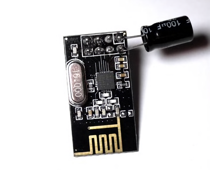
- Connecting a capacitor to the chip to 3, 3 V(+), and GND (-) ground. It is better to choose a capacity of 10 μF or more.
- Additional 3.3V voltage source.
- Designing a separate board, installing the nRF24L01, and adding 1 and 10 uF capacitors to it.
- Using YourDuinoRobo1, which has an additional 3.3V regulator.
Connecting nRF24L01 to the Arduino
The MOSI pin from the nRF24L01 board connects to pin 11 for Arduino Uno, Nano and to 51 for Arduino Mega. The SCK pin should be connected to pin 13 for Arduino Uno, Nano, and 52 for Arduino Mega. MISO – to 12 for Arduino Uno, Nano, and 50 for Arduino Mega. The CE and CSN pins are connected to any digital pin of the Arduino. The power supply is at 3.3V. If you use an Arduino Mini board, you will have to use an external voltage regulator as the board does not have a 3.3V output. You can also add a capacitor of 10µF or more to the power pins to ensure stable and quality operation. The module with the soldered capacitor is shown in the picture.
The appearance of the scheme is shown in the figure below.
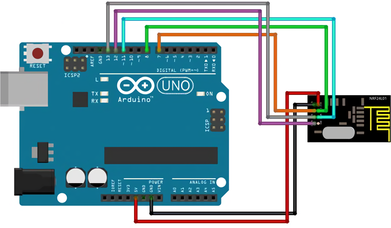
When connecting, it is important not to mix up the voltage – 5 volts can damage the module.
Connecting to the Arduino With the nRF24L01 Adapter
The adapter is specially designed for the NRF24L01+. It has a special voltage regulator and conveniently located outputs to the controllers and Arduino boards.
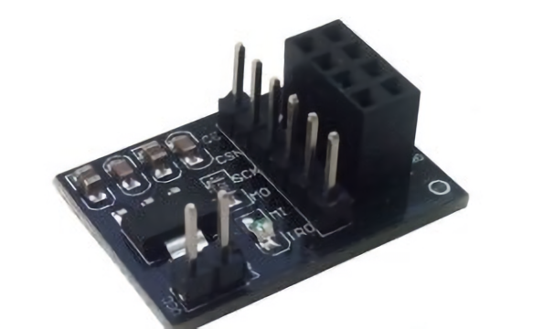
As you can see, there are 2 kinds of connectors on the adapter. The double row connector is used to connect the radio module, and the single row connector is used to connect to the Arduino. The outputs for power (5V) and ground are located separately.
To connect the NRF24L01+ radio module, you have to insert it into the corresponding two-level connector. With the wires, the adapter is connected to the Arduino board to the same pins that are needed to connect directly to the module. For example, to connect to Arduino Uno, Nano: MISO-12, MOSI-11, SCK-13, CE pins to D10 and CSN to D9, VCC pin to Arduino (+5V), and GND pin to Arduino (GND).
Programming nRF24L01
To write the sketches in the Arduino IDE, you need to install two libraries – RF24 and SerialFlow. The first one is needed to work with the module. The second one is for batch data transfer.
Example program for the transmitter. First, you create an object of the SerialFlow class:
SerialFlow rd(9,10);
In this line, 9 and 10 are free pins from the Arduino, to which the CN and CSN pins are connected.
The format of the transmitted packets is set in the setup function:
rd.setPacketFormat(2, 1);
The first argument (in this case, number 2) defines the size of the number to be transmitted. For this particular case, the number ranges from 0 to 655535 and takes up 2 bytes. For 0 to 255, it will take 1 byte. The second argument is the number of numbers.
Next you need to configure the transmitter and receiver addresses:
rd.begin(0xF0F0F0F0E1LL,0xF0F0F0F0D2LL);
The first argument writes the transmitter address, the second the receiver address.
The loop loop does the sending of the packets.
Here is an example of a program for the receiver. The receiver has to signal when it receives data. The data will be sent to the Arduino IDE port monitor.
In the code, you also write a SerialFlow object and set up the necessary parameters for the data packet. The changes take place in the line.
rd.begin(0xF0F0F0F0D2LL,0xF0F0F0F0E1LL);
Now the first argument should be the receiver’s address, and the second should be the address of the transmitter.
After loading the program on both modules, if all actions are correct, the timer value in milliseconds will appear in the window on the transmitter.
In addition to the RF24 and SerialFlow libraries, there is another one – the Mirf library. Again, the convenience of work determines the choice of one or the other library.
Operators for transferring data between two modules using the Mirf library:
payload = PAYLOAD;– sets the size of the buffer for receiving. There is a restriction on payload – the maximum size is 32 bytes.setRADDR((byte*)'serv1′);– selection of the receiver address (size not less than 3 bytes and not more than 5 bytes).setTADDR((byte *)'clie1′);– selection of the transmitter address (size at least 3 bytes and no more than 5 bytes). The data packet transmission on the first module is set to addressMirf.setTADDR((byte *)'clie1′), then the packet is sent to the second module. The second module thensets Mirf.setTADDR((byte *)'serv1′)and returns a response to the first module.isSending()– check for the end of data transfer.dataReady()– check for incoming packet receipt.getData((byte *) &data);– reading the received packets into the variable data.send((byte *) &data);– sending command to send the packet. The address where the variables are located is specified in the library. After that, it is copied into memory, and the user finally gets access to the data passed through the variables. The method is convenient because you can pass any type of data, including structures.
Transferring nRF24L01 Structures
Structures are convenient because you can write many variables in them and send them to another device at once. The code must be written in such a way that the Arduino transmits the command down the chain to the other modules. Each module knows only its address and the address of the next module.
When working with structures, you must carefully calculate their size and specify PAYLOAD. The total size of the structure will be equal to the sum of all sizes of its constituent variables.
The main elements of the code are:
#define ADDR "mod0" //the address of the module is specified

#define NEXT "mod1" //define the address of the next module

boolean iamfirst=true;//does this module start the chain?

#define PAYLOAD 5 //size payload
All modules will end up with the same sketch with only the ADDR, NEXT, and iamfirst variables being different.
Related Video: Arduino Wireless Communication – nRF24L01 Tutorial
Conclusion
The wireless module nRF24L01 cannot be called an easy-to-learn device. Both connection and programming require certain skills. But the cost and availability of the module allow us to recommend it for those who are engaged in projects of the Internet of things or need simple tools for communications. By buying a special adapter for nRF24L01, you can greatly simplify the connection to the Arduino. And by using the libraries, you can simplify the code as much as possible. Try not to buy nRF24L01 modules cheaply from unknown vendors, and then you won’t have any problems with your projects.


